REMOVAL PROCEDURE 1. REMOVE TIMING CHAIN COVER SUB-ASSEMBLY (a) Remove the timing chain cover (See page 2. SET NO. 1 CYLINDER TO TDC / COMPRESSION
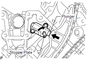
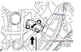
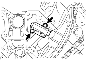
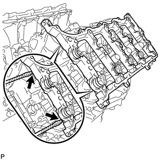
3. REMOVE NO. 1 CHAIN TENSIONER ASSEMBLY LH
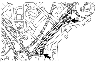
4. REMOVE NO. 1 CHAIN TENSIONER SLIPPER LH 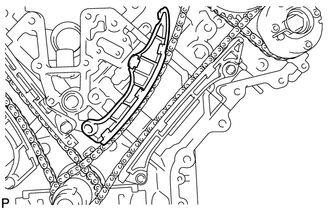 5. REMOVE NO. 1 CHAIN VIBRATION DAMPER LH
6. REMOVE NO. 1 CHAIN SUB-ASSEMBLY LH 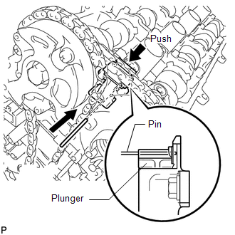 (a) While pushing down the No. 3 chain tensioner, insert a pin of φ1.0 mm (0.0394 in.) into the hole to fix it in place.
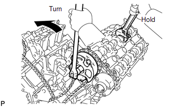
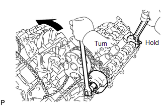
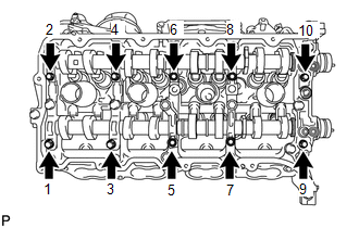
(d) Remove the 2 bolts. Then with the No. 1 and No. 2 chains still connected to the gears, remove the camshaft timing gear, camshaft timing exhaust gear and crankshaft timing sprocket LH. (e) Remove the No. 1 and No. 2 chains from the gears. 7. REMOVE NO. 3 CHAIN TENSIONER ASSEMBLY 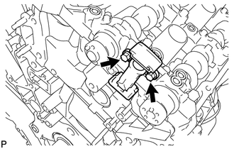 (a) Remove the 2 bolts and chain tensioner. 8. REMOVE CAMSHAFT BEARING CAP LH 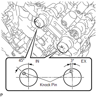 (a) Make sure that the knock pin of the camshaft is positioned as shown in the illustration.
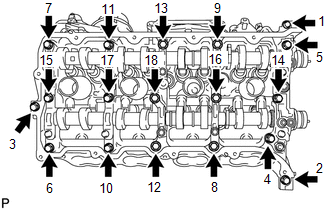
(d) Remove the 6 bearing caps. HINT: Arrange the removed parts in the correct order. (e) Remove the No. 3 and No. 4 camshafts. 9. REMOVE CAMSHAFT HOUSING SUB-ASSEMBLY LH
|
Toyota Tundra Service Manual > Sfi System: Precaution
PRECAUTION 1. INITIALIZATION NOTICE: Perform Reset Memory (AT initialization) for 2WD when replacing the automatic transmission assembly, engine assembly or ECM (See page ). Perform Reset Memory (AT initialization) for 4WD when replacing the automatic transmission assembly, engine assembly or ECM (S ...

 ).
).