
REPLACEMENT PROCEDURE 1. REPLACE STRAIGHT PIN NOTICE: It is not necessary to remove the straight pin unless it is being replaced. (a) Remove the straight pins. (b) Using a plastic-faced hammer, tap in new straight pins to the cylinder block. 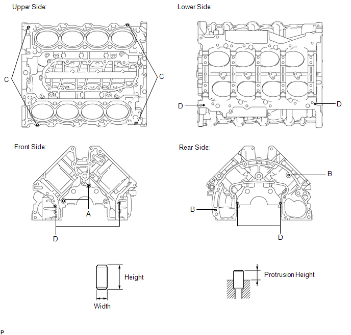 Standard Straight Pin:
|
Toyota Tundra Service Manual > Navigation Receiver(for Column Shift Type): Removal
REMOVAL PROCEDURE 1. PRECAUTION NOTICE: After turning the ignition switch off, waiting time may be required before disconnecting the cable from the battery terminal. Therefore, make sure to read the disconnecting the cable from the battery terminal notice before proceeding with work (See page ). 2. ...


