REMOVAL PROCEDURE 1. REMOVE EXHAUST MANIFOLD SUB-ASSEMBLY LH (a) Remove the exhaust manifold LH (See page 2. REMOVE CAMSHAFTS (for Bank 1) (a) Remove the camshafts (See page
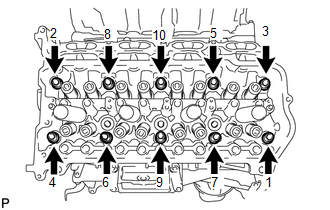
3. REMOVE NO. 1 VALVE ROCKER ARM SUB-ASSEMBLY (a) Remove the 16 valve rocker arms from the cylinder head. HINT: Arrange the removed parts in the correct order. 4. REMOVE VALVE LASH ADJUSTER ASSEMBLY (a) Remove the 16 valve lash adjusters from the cylinder head. HINT: Arrange the removed parts in the correct order. 5. REMOVE VALVE STEM CAP (a) Remove the 16 valve stem caps from the cylinder head. HINT: Arrange the removed parts in the correct order. 6. REMOVE CYLINDER HEAD SUB-ASSEMBLY LH
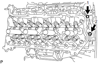
7. REMOVE CYLINDER HEAD GASKET LH |
Toyota Tundra Service Manual > Shift Lever Assembly(for Column Shift Type): Removal
REMOVAL PROCEDURE 1. REMOVE TURN SIGNAL SWITCH ASSEMBLY WITH SPIRAL CABLE SUB-ASSEMBLY (See page ) 2. REMOVE COLUMN SHIFT ASSEMBLY (a) Move the shift lever to N. (b) Disconnect the column shift transmission control cable end from the column shift. (c) Disconnect the connector and detach the harness ...

 ).
).