REMOVAL PROCEDURE 1. REMOVE EXHAUST MANIFOLD SUB-ASSEMBLY RH (a) Remove the exhaust manifold RH (See page 2. REMOVE CAMSHAFTS (for Bank 2) (a) Remove the camshafts (See page
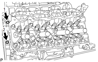
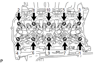
3. REMOVE NO. 1 VALVE ROCKER ARM SUB-ASSEMBLY (a) Remove the 16 valve rocker arms from the cylinder head. HINT: Arrange the removed parts in the correct order. 4. REMOVE VALVE LASH ADJUSTER ASSEMBLY (a) Remove the 16 valve lash adjusters from the cylinder head. HINT: Arrange the removed parts in the correct order. 5. REMOVE VALVE STEM CAP (a) Remove the 16 valve stem caps from the cylinder head. HINT: Arrange the removed parts in the correct order. 6. REMOVE CYLINDER HEAD SUB-ASSEMBLY RH
7. REMOVE CYLINDER HEAD GASKET RH |
Toyota Tundra Service Manual > 1ur-fe Intake: Vacuum Switching Valve(for Acis)
On-vehicle InspectionON-VEHICLE INSPECTION PROCEDURE 1. REMOVE V-BANK COVER SUB-ASSEMBLY 2. INSPECT VACUUM SWITCHING VALVE ASSEMBLY (for ACIS) (a) Disconnect the vacuum switching valve connector. (b) Measure the resistance according to the value(s) in the table below. Standard Resistance: Tester Co ...

 ).
).