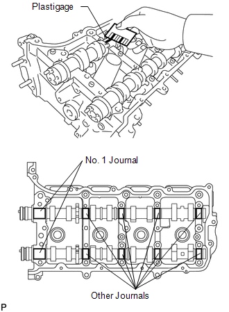
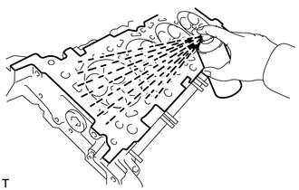
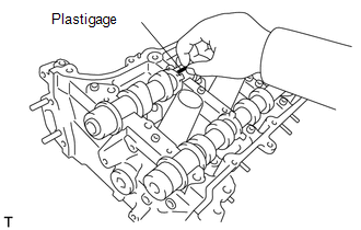
INSPECTION PROCEDURE 1. INSPECT CAMSHAFT OIL CLEARANCE (a) Clean the bearing caps, camshaft housing and camshaft journals. (b) Place the camshafts on the camshaft housing.
(d) Install the camshaft bearing caps (See page
NOTICE: Do not turn the camshaft. (e) Install the camshaft housing (See page NOTICE: Do not turn the camshaft. (f) Remove the camshaft bearing caps (See page
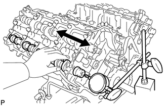
2. INSPECT CAMSHAFT THRUST CLEARANCE (a) Inspect the LH side camshafts. (1) Install the LH side camshafts.
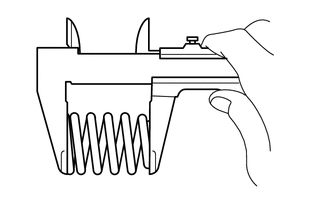
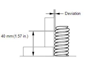
(b) Inspect the RH side camshafts. (1) Install the RH side camshafts. (2) Using a dial indicator, measure the thrust clearance while moving the camshaft back and forth. Standard thrust clearance: 0.08 to 0.135 mm (0.00315 to 0.00531 in.) Maximum thrust clearance: 0.15 mm (0.00591 in.) If the thrust clearance is more than the maximum, replace the camshaft housing. If the thrust surface is damaged, replace the camshaft. 3. INSPECT COMPRESSION SPRING
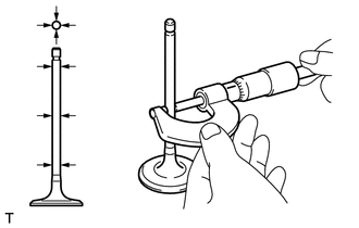
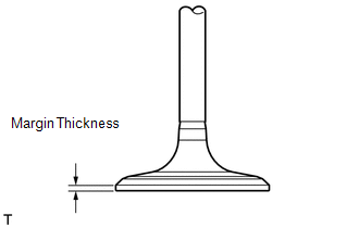
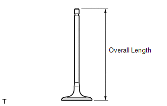
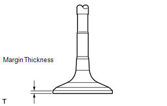
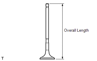
4. INSPECT INTAKE VALVE
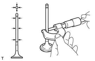
5. INSPECT EXHAUST VALVE
6. INSPECT VALVE GUIDE BUSH OIL CLEARANCE 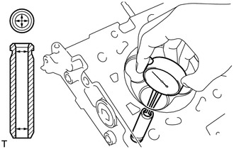 (a) Using a caliper gauge, measure the inside diameter of the guide bush. Standard bush inside diameter: 5.51 to 5.53 mm (0.217 to 0.218 in.) (b) Subtract the valve stem diameter measurement from the guide bush inside diameter measurement. Standard Oil Clearance:
Maximum Oil Clearance:
If the oil clearance is more than the maximum, replace the valve and guide bush. 7. INSPECT INTAKE VALVE SEAT 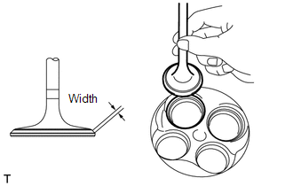
(a) Apply a light coat of Prussian blue to the valve face. (b) Lightly press the valve face against the valve seat. HINT: Do not rotate the valve while pressing the valve. (c) Check the valve face and valve seat. (1) Check that the contact surfaces of the valve seat and valve face are in the middle area of their respective surfaces, with the width between 1.1 to 1.5 mm (0.0433 to 0.0591 in.). If not, correct the valve seat. (2) Check that the contact surfaces of the valve seat and valve face are even around the entire valve seat. If not, correct the valve seat. 8. INSPECT EXHAUST VALVE SEAT 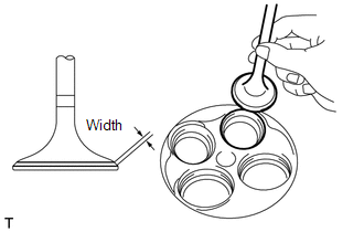 (a) Apply a light coat of Prussian blue to the valve face. (b) Lightly press the valve face against the valve seat. HINT: Do not rotate the valve while pressing the valve. (c) Check the valve face and valve seat. (1) Check that the contact surfaces of the valve seat and valve face are in the middle area of their respective surfaces, with the width between 1.1 to 1.5 mm (0.0433 to 0.0591 in.). If not, correct the valve seat. (2) Check that the contact surfaces of the valve seat and valve face are even around the entire valve seat. If not, correct the valve seat. 9. INSPECT CYLINDER HEAD SUB-ASSEMBLY 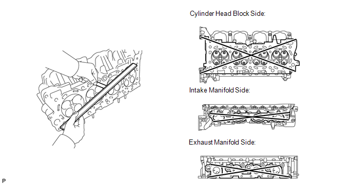 (a) Using a precision straightedge and feeler gauge, measure the warpage of the contact surfaces of the cylinder block and manifold. Standard Warpage:
Maximum warpage: 0.10 mm (0.00394 in.) If the warpage is more than the maximum, replace the cylinder head.
|
Toyota Tundra Service Manual > Side Airbag Sensor(for Double Cab): On-vehicle Inspection
ON-VEHICLE INSPECTION PROCEDURE 1. CHECK REAR AIRBAG SENSOR (VEHICLE NOT INVOLVED IN COLLISION) (a) Perform a diagnostic system check (see page ). 2. CHECK REAR AIRBAG SENSOR (VEHICLE INVOLVED IN COLLISION AND AIRBAG HAS NOT DEPLOYED) (a) Perform a diagnostic system check (see page ). (b) When the q ...

 ).
).