COMPONENTS ILLUSTRATION 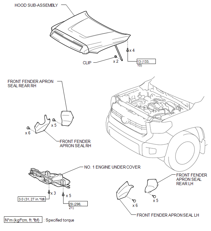 ILLUSTRATION 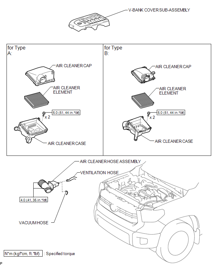 ILLUSTRATION 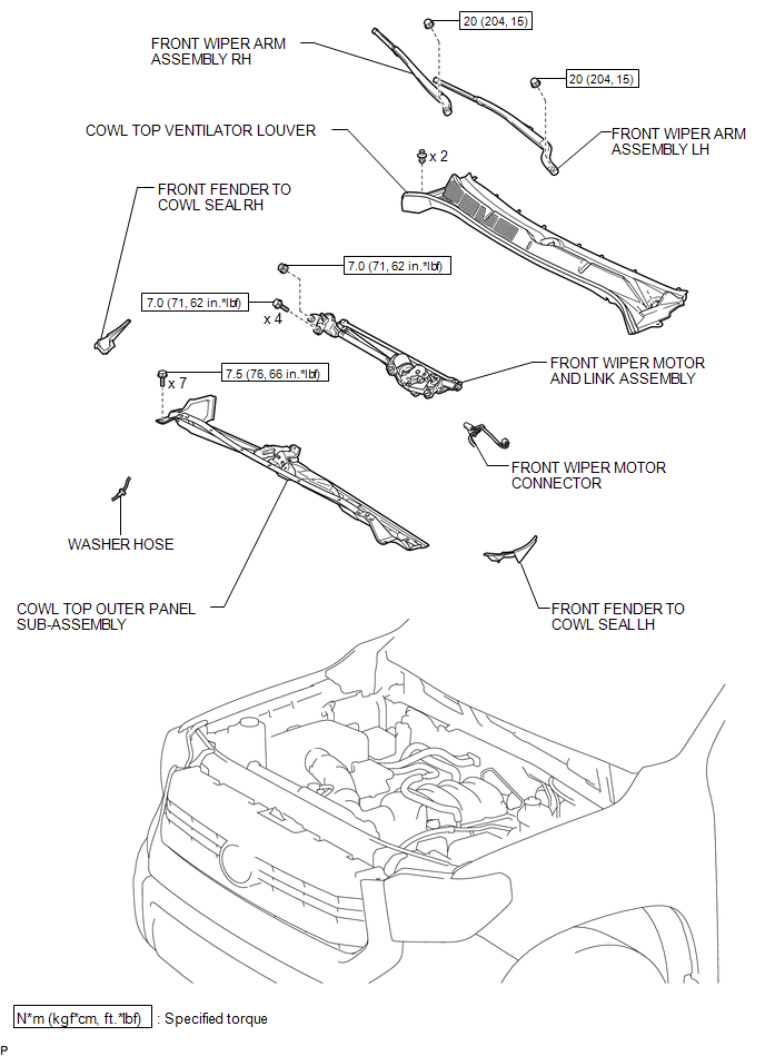 ILLUSTRATION 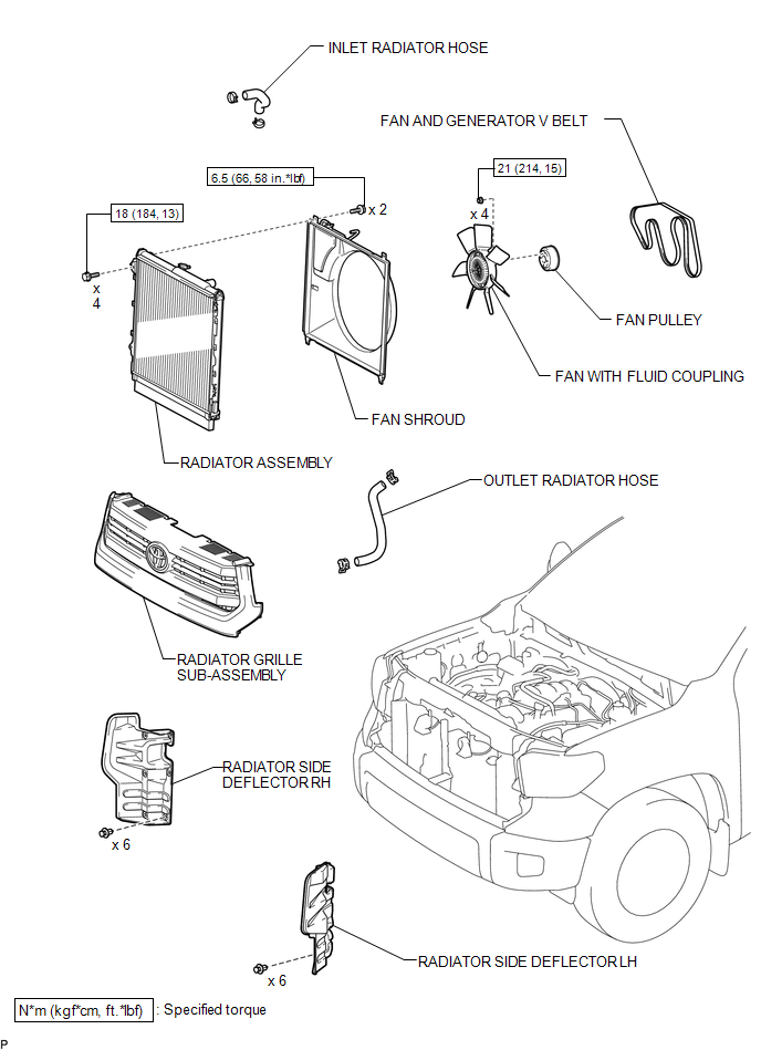 ILLUSTRATION 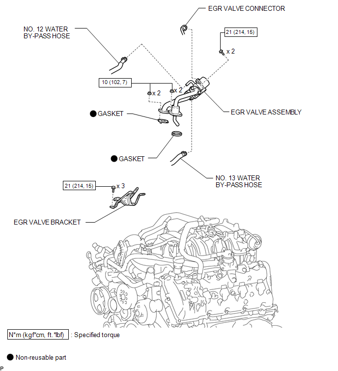 ILLUSTRATION 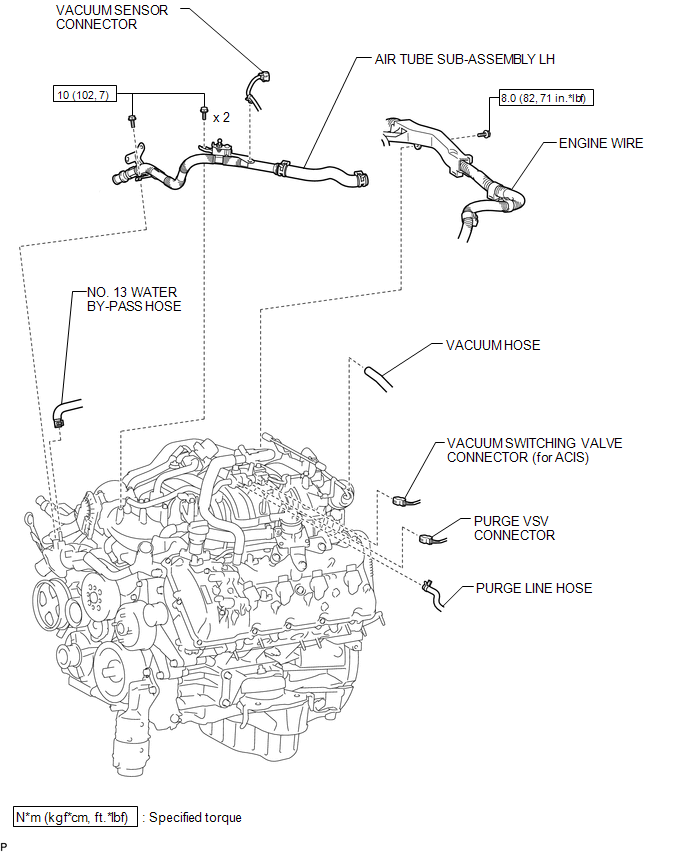 ILLUSTRATION 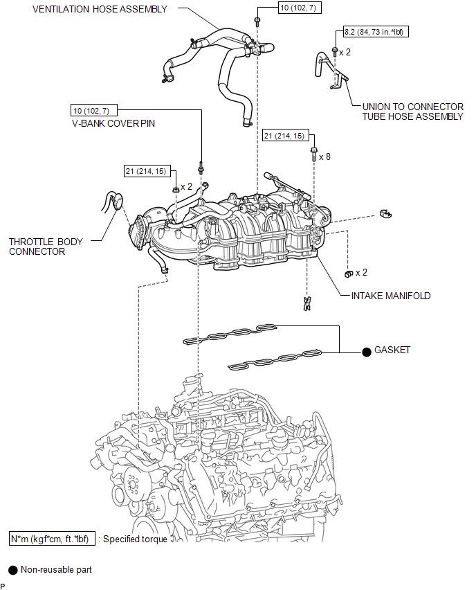 ILLUSTRATION 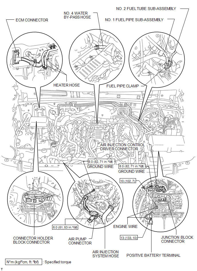 ILLUSTRATION 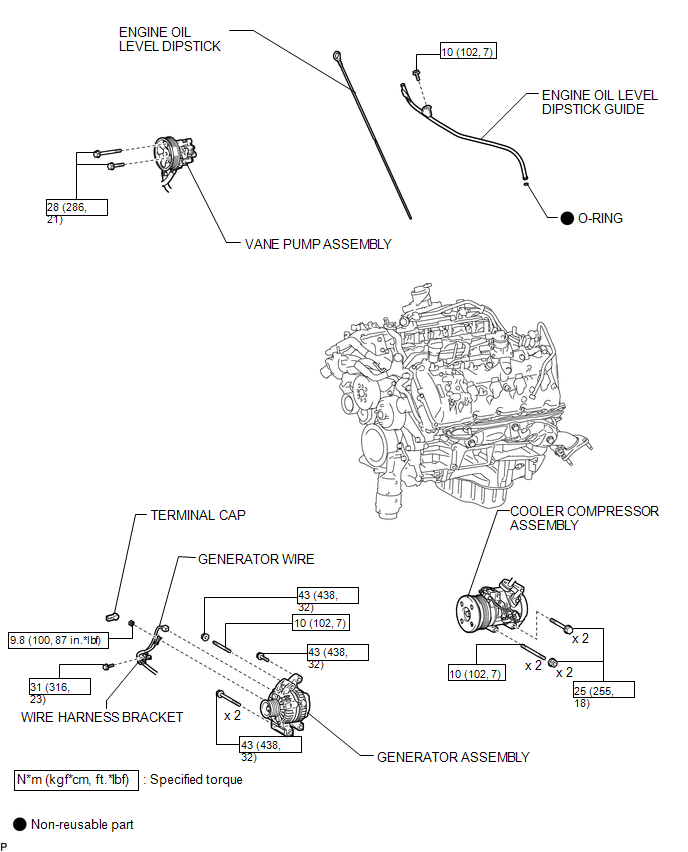 ILLUSTRATION 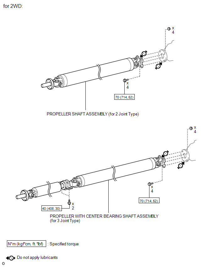 ILLUSTRATION 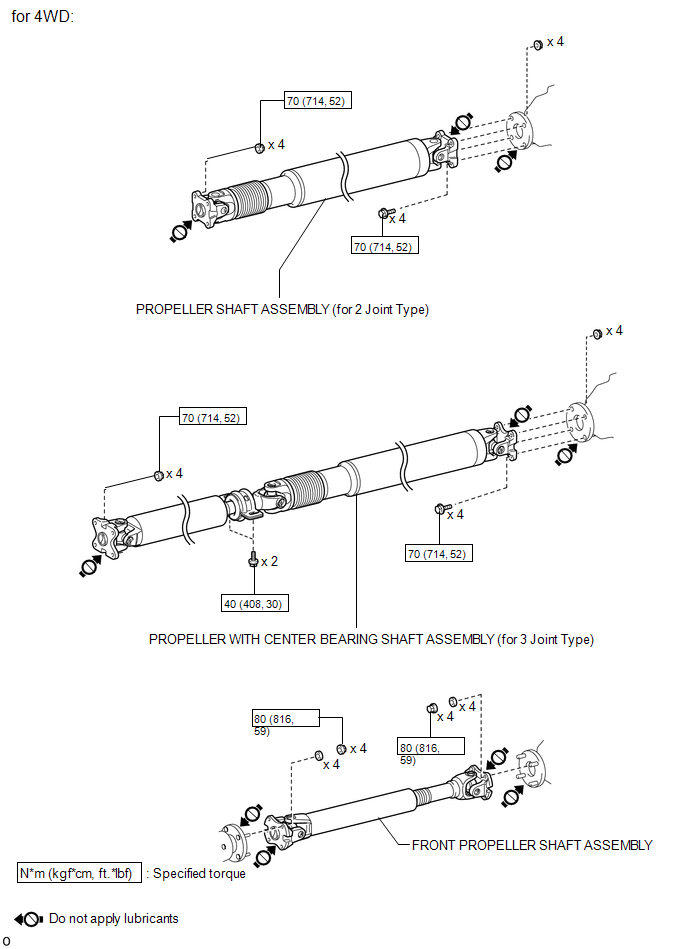 ILLUSTRATION 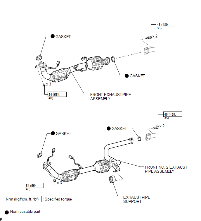 ILLUSTRATION 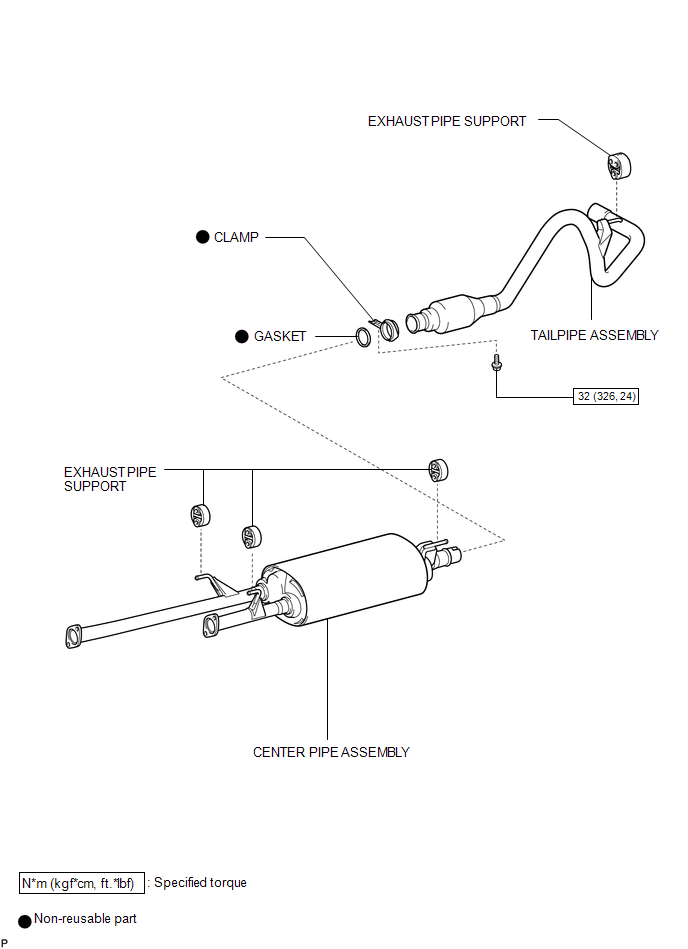 ILLUSTRATION 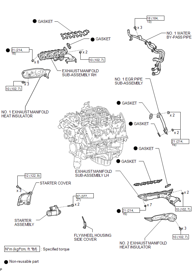 ILLUSTRATION 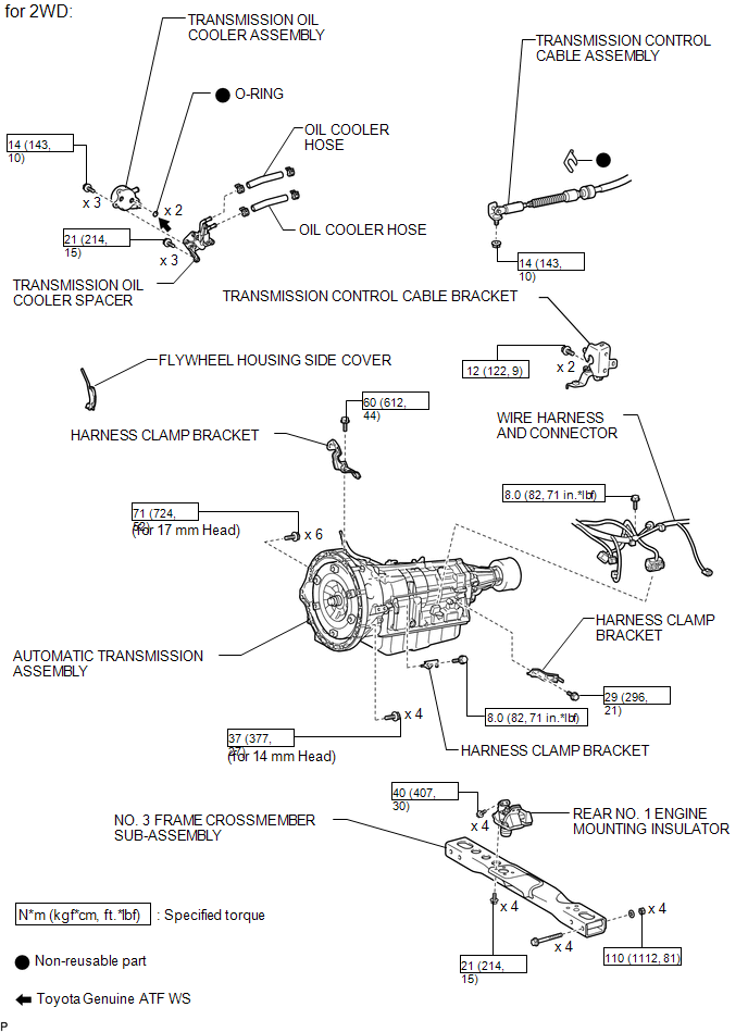 ILLUSTRATION 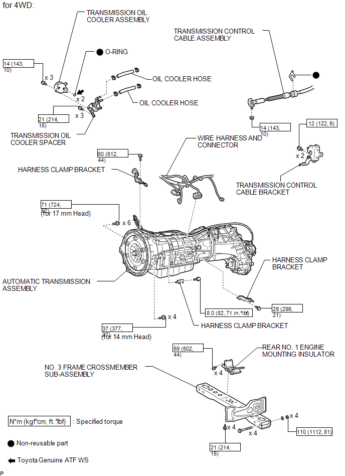 ILLUSTRATION 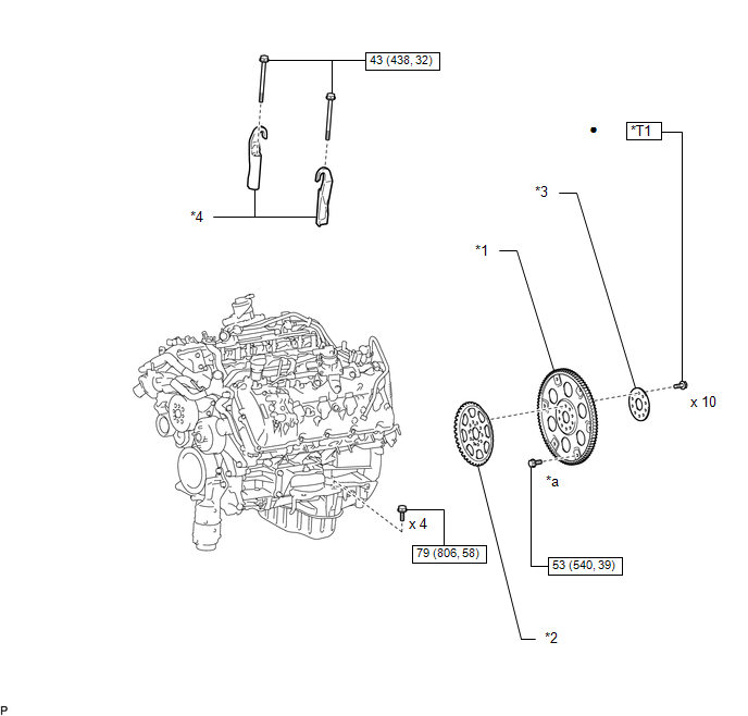
|
Toyota Tundra Service Manual > Lighting System: Door Courtesy Switch Circuit
DESCRIPTION The main body ECU (multiplex network body ECU) detects the condition of the door courtesy light switch assembly. WIRING DIAGRAM PROCEDURE 1. READ VALUE USING TECHSTREAM (a) Using the Techstream, read the Data List. Click here Main Body Tester Display Measurement Item / Range Normal Condi ...


