INSTALLATION CAUTION / NOTICE / HINT
HINT: Perform "Inspection After Repairs" after replacing the fuel pump.
Click here  PROCEDURE
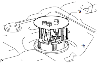
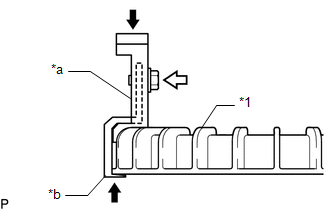
1. INSTALL FUEL SUCTION WITH PUMP AND GAUGE TUBE ASSEMBLY (a) Apply a light coat of gasoline to a new gasket, and install it to the fuel tank assembly.
| (b) Align the protrusion of the fuel suction with pump and gauge tube assembly with the groove of the fuel tank assembly. |
|
(c) Install the fuel suction with pump and gauge tube into the fuel tank.
NOTICE: Be careful not to bend the arm of the fuel sender gauge.
| (d) Apply a co-rotation prevention check mark to the fuel suction with pump and gauge tube assembly.
HINT: Perform this procedure when replacement of the fuel suction with pump and gauge tube assembly is necessary. |
 |
|
*a | Co-rotation Prevention Check Mark | | |
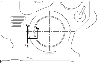
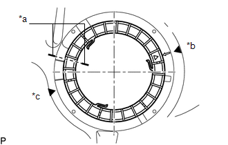
| (e)
Temporarily place the fuel pump gauge retainer by aligning the
rotational start point mark of a new fuel pump gauge retainer with the
rotational start point mark of the fuel tank assembly while pressing the
fuel suction with pump and gauge tube into the fuel tank assembly. |
 |
|
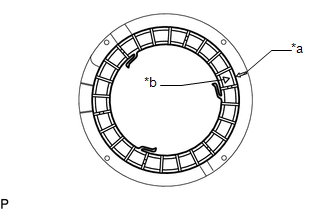
*a | Rotational Start Point Mark (Fuel Tank Assembly Side) | |
*b | Rotational Start Point Mark (Fuel Pump Gauge Retainer Side) | | |
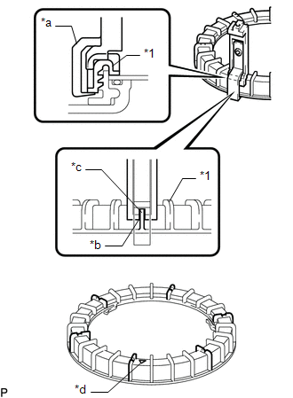
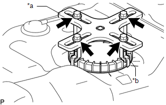
| (f) Set 4 SSTs (claw sets) to the fuel pump gauge retainer and temporarily install.
SST: 09808-14031 09808-01080 09808-01090 09808-01100
NOTICE:
- Align the cutout of SST (claw set) to the rib of the fuel pump gauge retainer.
- Do not place SST on the rotational start point mark of the fuel pump
gauge retainer, otherwise SST (claw set) cannot be set correctly.
|
 |
|
*1 | Fuel Pump Gauge Retainer | |
*a | SST (claw set) | |
*b | Rib | |
*c | Cutout | |
*d | SST (Claw Set) Incorrect Installation Point (Rotational Start Point Mark of Fuel Pump Gauge Retainer) | | |
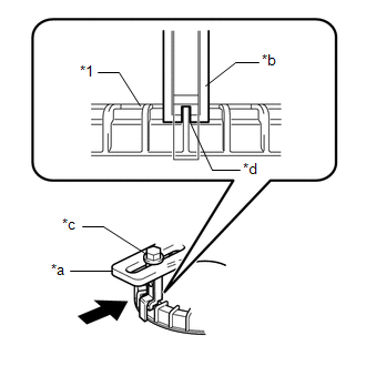
(g) While firmly pressing the claw of SST into rib of the fuel pump gauge retainer, tighten the bolt.
|
*1 | Fuel Pump Gauge Retainer | |
*a | SST (Claw Set) | |
*b | Hook |
 |
Press |
 |
SST (Bolt) | (h) Temporarily install SST (plate) to SST (claw set) with 4 SSTs (bolts).
|
*a | SST (Plate) | |
*b | SST (Claw Set) | |
|
SST (Bolt) |
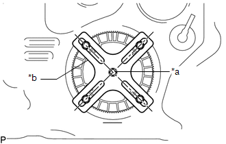
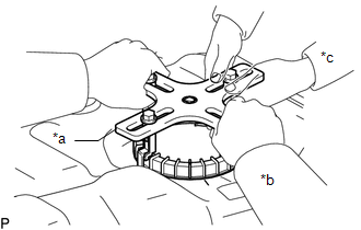
| (i)
Adjust the position of SST (plate) so that the setting hole of SST
(handle) aligns with the center of the fuel pump gauge retainer. |
 |
|
*a | Center of Fuel Pump Gauge Retainer | |
*b | SST (Plate) | | |
(j) While firmly pressing the SST (claw set) into rib of the fuel pump gauge retainer, tighten SST (bolt).
|
*1 | Fuel Pump Gauge Retainer | |
*a | SST (Plate) | |
*b | SST (Claw Set) | |
*c | SST (Bolt) | |
*d | Rib | |
|
Press |
| (k)
While one person presses the fuel suction with pump and gauge tube
assembly into the fuel tank assembly, have another person firmly press
the fuel pump gauge retainer into the threads of the fuel tank assembly
and tighten approximately one and a half turns.
NOTICE:
- Do not use any tools other than SST, such as a screwdriver, etc.
- Do not use excessive force when pressing down on SST, as the fuel
suction with pump and gauge tube assembly will place excessive force on
the pump gauge retainer and be difficult to remove, and parts may be
damaged.
- Do not use an impact wrench or turn the SST handle with excessive force, as parts may be damaged.
- Do not rotate the fuel pump gauge retainer when the co-rotation prevention check mark is out of place.
|
 |
|
*a | Co-rotation Prevention Check Mark | |
*b | Tightening Start Position | |
*c | One and Half Rotation Position | | |
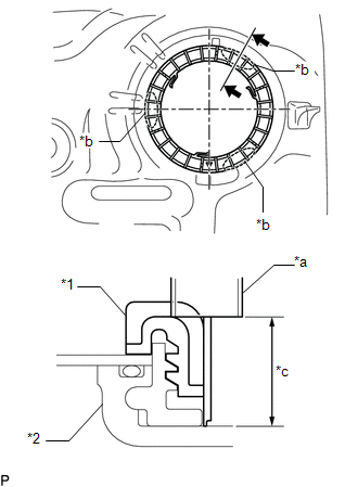
(l) Check the tightening condition of the fuel pump gauge retainer.
| (1)
Using a vernier caliper, measure the upper surface dimensions of the
fuel tank assembly at the 3 positions as shown in the illustration. Standard:
Measurement difference is within 3 mm. NOTICE: If
the measurement difference is approximately 6 mm, the threads
misaligned by 1 threads (6 mm) and the fuel pump gauge retainer must be
installed again. |
 |
|
*1 | Fuel Pump Gauge Retainer | |
*2 | Fuel Tank Assembly | |
*a | Vernier Caliper | |
*b | Measurement Position | |
*c | Measurement Height | | |
| (m)
While one person presses the fuel tank vent tube assembly into the fuel
tank assembly, have another person slowly tighten approximately half
turns. |
 |
|
*a | SST (Plate) | |
*b | Person in Charge of Tightening | |
*c | Person in Charge of Supporting | | |
(n) Install SST (handle) to SST (plate). SST: 09808-14031 09808-01010
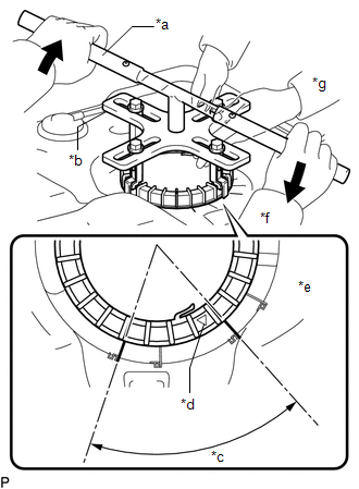
09808-01020 (o)
While one person presses the fuel suction with pump and gauge tube
assembly onto the fuel tank sub-assembly, have another person use SST
(handle) and slowly tighten the fuel pump gauge retainer until it
reaches the tightening complete position.
|
*a | SST (Handle) | |
*b | SST (Plate) | |
*c | Tightening Complete Position | |
*d | Rotational Start Point Mark of Fuel Pump Gauge Retainer | |
*e | Rotational Start Point Mark of Fuel Tank Assembly | |
*f | Person in Charge of Tightening | |
*g | Person in Charge of Supporting | |
|
Tighten | (p) Install the 2 fuel tank tubes with the 2 tube joint clips.
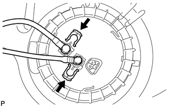
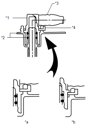
|
*1 | Fuel Tube Joint | |
*2 | O-Ring | |
*3 | Fuel Tube | |
*4 | Fuel Tube Joint Clip | |
*a | CORRECT | |
*b | INCORRECT |
- Check that there are no scratches or foreign objects on the connecting parts.
- Check that the fuel tube joints are inserted securely.
- Check that the tube joint clips are on the collars of the fuel tube joints.
- After installing the tube joint clips, check that the fuel tube joints have not been pulled off.
2. INSTALL FUEL TANK ASSEMBLY Click here
|