Components COMPONENTS ILLUSTRATION 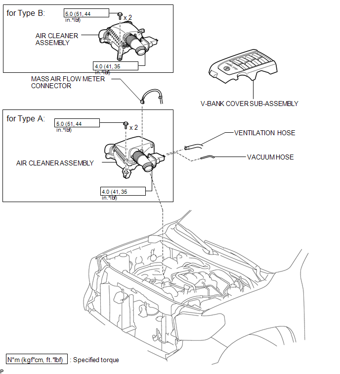 ILLUSTRATION 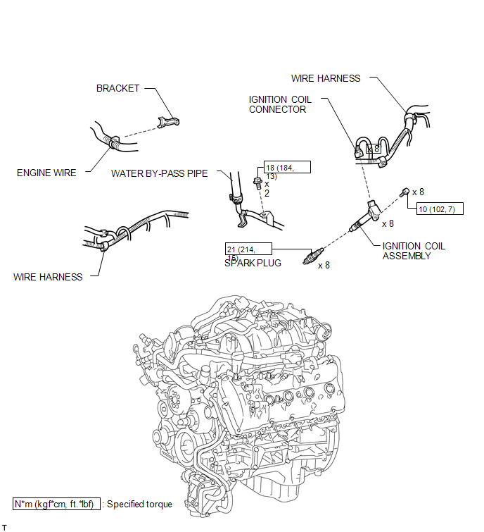 Installation INSTALLATION CAUTION / NOTICE / HINT HINT: Perform "Inspection After Repairs" after replacing the spark plug or ignition coil assembly (See page
PROCEDURE 1. INSTALL SPARK PLUG HINT: Perform "Inspection After Repairs" after replacing the spark plug (See page
(a) Using a 16 mm plug wrench, install the 8 spark plugs. Torque: 21 N·m {214 kgf·cm, 15 ft·lbf} 2. INSTALL IGNITION COIL ASSEMBLY HINT: Perform "Inspection After Repairs" after replacing the ignition coil assembly (See page
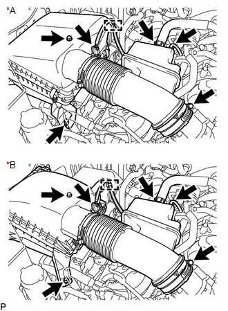
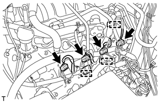
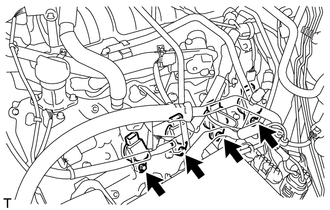
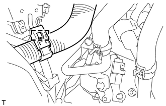
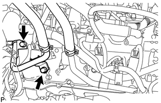
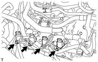
(a) for Bank 1: (1) Install the 4 ignition coil assemblies with the 4 bolts. Torque: 10 N·m {102 kgf·cm, 7 ft·lbf} (2) Connect the 4 ignition coil connectors. (3) Attach the 3 wire harness clamps. (b) for Bank 2: (1) Install the 4 ignition coil assemblies with the 4 bolts. Torque: 10 N·m {102 kgf·cm, 7 ft·lbf} (2) Attach the 2 wire harness clamps and connect the 4 ignition coil connectors. (3) Connect the water by-pass pipe with the 2 bolts. Torque: 18 N·m {184 kgf·cm, 13 ft·lbf} (4) Attach the engine wire harness clamp. 3. INSTALL AIR CLEANER ASSEMBLY (a) Install the air cleaner assembly with the 2 bolts. Torque: 5.0 N·m {51 kgf·cm, 44 in·lbf} (b) Tighten the hose clamp. Torque: 4.0 N·m {41 kgf·cm, 35 in·lbf} (c) Connect the ventilation hose and vacuum hose. (d) Attach the clamp and connect the mass air flow meter connector. 4. INSTALL V-BANK COVER SUB-ASSEMBLY Removal REMOVAL PROCEDURE 1. REMOVE V-BANK COVER SUB-ASSEMBLY 2. REMOVE AIR CLEANER ASSEMBLY
(b) Disconnect the ventilation hose and vacuum hose. (c) Loosen the hose clamp. (d) Remove the 2 bolts and air cleaner assembly. 3. REMOVE IGNITION COIL ASSEMBLY (a) for Bank 1:
(2) Disconnect the 4 ignition coil connectors.
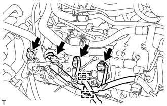
(b) for Bank 2:
(2) Disconnect the 4 ignition coil connectors.
4. REMOVE SPARK PLUG (a) Using a 16 mm plug wrench, remove the 8 spark plugs. |
Toyota Tundra Service Manual > Wireless Door Lock Control System: How To Proceed With Troubleshooting
CAUTION / NOTICE / HINT HINT: The wireless door lock control system troubleshooting procedures are based on the premise that the power door lock system is operating normally. Check the power door lock system first before troubleshooting the wireless door lock control system. Click here Use these pro ...

 ).
).