Toyota Tundra Service Manual: Inspection

INSPECTION

PROCEDURE

1. INSPECT PARK/NEUTRAL POSITION SWITCH ASSEMBLY

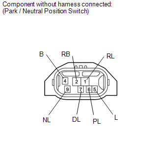
(a) Measure the resistance according to the value(s) in the table below.

Standard Resistance:

Tester Connection

Condition

Specified Condition

  • 2 (RB) - 6 (PL)
  • 4 (B) - 5 (L)

Shift lever in P

Below 1 Ω

2 (RB) - 1 (RL)

Shift lever in R

Below 1 Ω

  • 2 (RB) - 9 (NL)
  • 4 (B) - 5 (L)

Shift lever in N

Below 1 Ω

2 (RB) - 7 (DL)

Shift lever in D, S, "+" or "-"

Below 1 Ω

  • 2 (RB) - 6 (PL)
  • 4 (B) - 5 (L)

Shift lever not in P

10 kΩ or higher

2 (RB) - 1 (RL)

Shift lever not in R

10 kΩ or higher

  • 2 (RB) - 9 (NL)
  • 4 (B) - 5 (L)

Shift lever not in N

10 kΩ or higher

2 (RB) - 7 (DL)

Shift lever not in D, S, "+" or "-"

10 kΩ or higher

If the result is not as specified, replace the park/neutral position switch assembly.

    Components

    Installation

    See More:

    Toyota Tundra Service Manual > Power Door Lock Control System: All Doors LOCK/UNLOCK Functions do not Operate Via Door Control Switch
    DESCRIPTION The main body ECU (multiplex network body ECU) receives switch signals from the door control switch assembly on the driver and front passenger door and activates the door lock motor on each door according to these signals. WIRING DIAGRAM w/o Jam Protection Function: w/ Jam Protection Fun ...

    Toyota Tundra Owners Manual

    Toyota Tundra Service Manual

    © 2024 Copyright www.ttundra.com
    0.0128