REASSEMBLY PROCEDURE 1. INSTALL TRANSMISSION CONTROL SWITCH (P POSITION)  (a) Install the switch to the column shift control shift lever retainer with the 2 screws. 2. INSTALL TRANSMISSION CONTROL SWITCH (S POSITION) 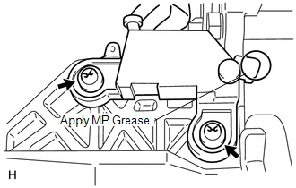 (a) Apply MP grease to the switch as shown in the illustration. (b) Install the switch to the column shift control shift lever retainer with the 2 screws.
3. CONNECT NO. 1 SHIFT LOCK PLATE SUB-ASSEMBLY  (a) Using a hammer, tap in the spring pin to connect the shift lock plate and shift lock solenoid. 4. INSTALL SHIFT LOCK SOLENOID 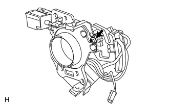 (a) Install the shift lock solenoid with No. 1 shift lock plate sub-assembly, 2 bushes and collar to the column shift control shift lever retainer with the screw. Torque: 1.2 N·m {12 kgf·cm, 11 in·lbf}
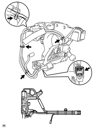
5. INSTALL COLUMN SHIFT SHIFT LEVER SUB-ASSEMBLY 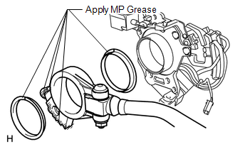 (a) Apply MP grease to the 2 lever selecting bushes as shown in the illustration. (b) Install the 2 lever selecting bushes and shift lever to the column shift control shift lever retainer. (c) Pass the wire harness of the shift lever through the control shaft tube clamp.
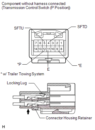
(f) w/ Trailer Towing System: Securely connect the 4 wire terminals to terminal 4 (SFTD), 5 (SFTU), 12 (P), 9 (E) and 11 (E) of the transmission control switch connector. Then push the connector housing retainer to lock it. (g) Fix the connector housing retainer of the connector in place. 6. INSTALL COLUMN SHIFT SHIFT LOCK RELEASE LINK 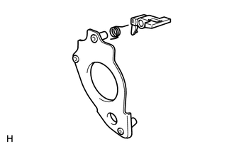 (a) Install the spring and shift lock release link to the shift lever plate. 7. INSTALL SHIFT LEVER PLATE SUB-ASSEMBLY 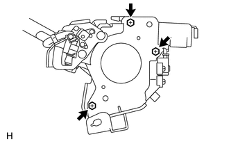 (a) Install the shift lever plate to the column shift control shift lever retainer with the 3 bolts. Torque: 2.3 N·m {23 kgf·cm, 20 in·lbf}
8. INSTALL COLUMN SHIFT LEVER COMPRESSION SPRING 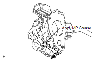 (a) Apply MP grease to the spring as shown in the illustration. (b) Temporarily install the spring to the column shift control shift lever retainer with the bolt.
9. INSTALL COLUMN SHIFT SHIFTING BELLCRANK ASSEMBLY 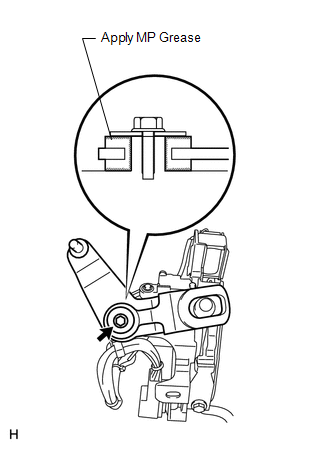 (a) Apply MP grease to the shifting bellcrank as shown in the illustration. (b) Install the shifting bellcrank with the bolt. Torque: 5.0 N·m {51 kgf·cm, 44 in·lbf} |
Toyota Tundra Service Manual > Airbag System: Diagnostic Trouble Code Chart
DIAGNOSTIC TROUBLE CODE CHART Airbag System DTC No. Detection Item Warning Indicate Test Mode / Check Mode Link B1160 Airbag ECU Malfunction1 Comes on Not applicable B1161 Airbag ECU Malfunction2 Comes on Not applicable B1162 Airbag ECU Malfunction3 Comes on Not applicable B1163 Airbag ECU Malfuncti ...