Components COMPONENTS ILLUSTRATION 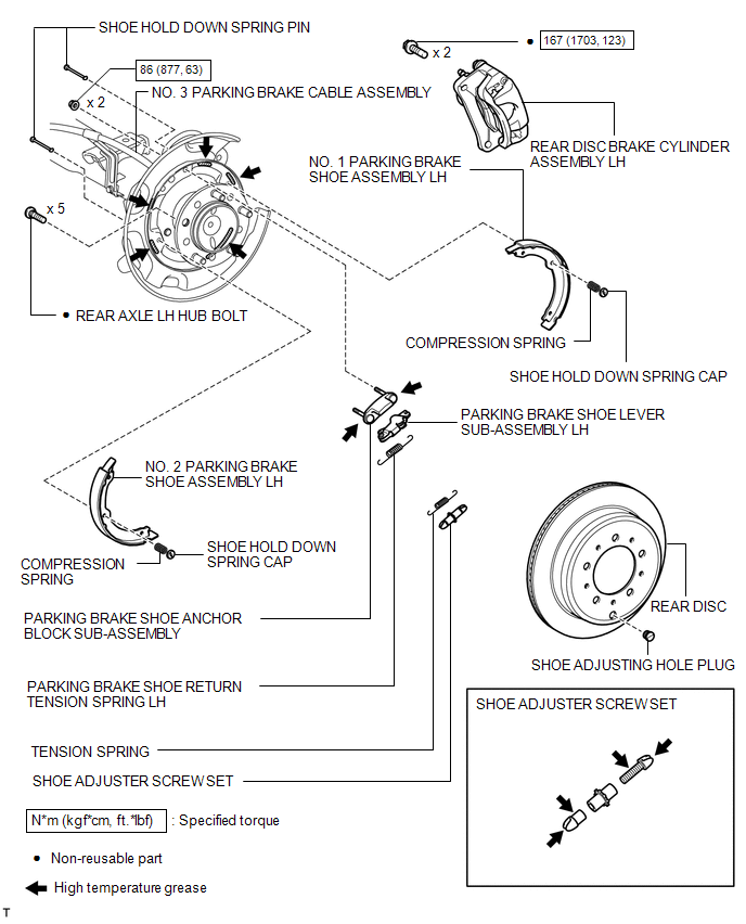 Replacement REPLACEMENT CAUTION / NOTICE / HINT HINT:
PROCEDURE 1. REMOVE REAR WHEEL LH 2. DISCONNECT REAR DISC BRAKE CYLINDER ASSEMBLY LH 3. REMOVE REAR DISC LH
4. REMOVE PARKING BRAKE SHOE RETURN TENSION SPRING LH 5. REMOVE NO. 1 PARKING BRAKE SHOE ASSEMBLY LH 6. REMOVE NO. 2 PARKING BRAKE SHOE ASSEMBLY LH 7. REMOVE PARKING BRAKE SHOE LEVER SUB-ASSEMBLY LH 8. REMOVE REAR AXLE LH HUB BOLT
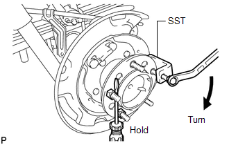
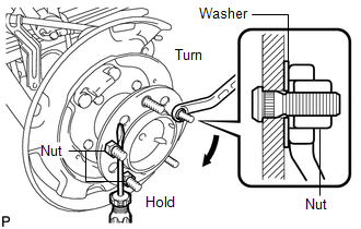
9. INSTALL REAR AXLE LH HUB BOLT
(b) Using a screwdriver or equivalent to hold the hub, turn the hub nut until the bottom surface of the hub bolt head touches the axle hub. (c) Remove the washer and hub nut. NOTICE: Do not damage the threads of the hub bolts. 10. INSTALL PARKING BRAKE SHOE LEVER SUB-ASSEMBLY LH 11. INSTALL NO. 2 PARKING BRAKE SHOE ASSEMBLY LH 12. INSTALL NO. 1 PARKING BRAKE SHOE ASSEMBLY LH 13. INSTALL PARKING BRAKE SHOE RETURN TENSION SPRING LH 14. CHECK PARKING BRAKE INSTALLATION 15. INSTALL REAR DISC LH
16. ADJUST PARKING BRAKE SHOE CLEARANCE 17. CONNECT REAR DISC BRAKE CYLINDER ASSEMBLY LH 18. INSTALL REAR WHEEL LH Torque: for Aluminum Wheel : 131 N·m {1336 kgf·cm, 97 ft·lbf} for Steel Wheel : 209 N·m {2131 kgf·cm, 154 ft·lbf} 19. CHECK PARKING BRAKE TRAVEL 20. ADJUST PARKING BRAKE TRAVEL |
Toyota Tundra Service Manual > Trailer Brake Control System: Parts Location
PARTS LOCATION ILLUSTRATION *A w/ Dynamic Radar Cruise Control System - - *1 ECM *2 BRAKE ACTUATOR ASSEMBLY - SKID CONTROL ECU *3 ENGINE ROOM RELAY BLOCK AND JUNCTION BLOCK - TOW BRK FUSE *4 TRAILER SOCKET *5 MILLIMETER WAVE RADAR SENSOR ASSEMBLY - - ILLUSTRATION *1 TRAILER BRAKE CONTROL SWITCH - GA ...