DESCRIPTION The distance control switch is used to set the distance for vehicle-to-vehicle distance control mode. The distance control switch is installed in the steering pad switch assembly. The vehicle-to-vehicle distance set value can be changed by operating the steering pad switch assembly (distance control switch) while the dynamic radar cruise control system is controlling vehicle speed in vehicle-to-vehicle distance control mode. WIRING DIAGRAM 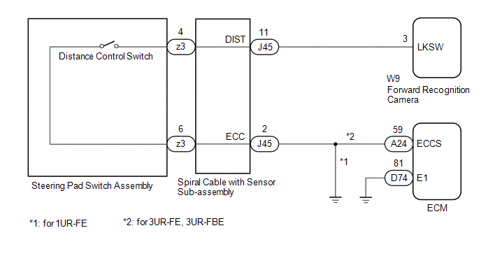 CAUTION / NOTICE / HINT NOTICE:
PROCEDURE
(a) Connect the Techstream to the DLC3. (b) Turn the ignition switch to ON. (c) Turn the Techstream on. (d) Enter the following menus: Powertrain / Radar Cruise 2 / Data List. (e) Read the Data List according to the display on the Techstream. Powertrain > Radar Cruise2 > Data List
OK: The Data List item shown in the table changes according to the operation of the steering pad switch assembly (distance control switch).
(a) Remove the steering pad switch assembly. Click here (b) Inspect the steering pad switch assembly. Click here
(a) Remove the spiral cable with sensor sub-assembly. Click here
(b) Inspect the spiral cable with sensor sub-assembly. Click here
(a) Disconnect the J45 spiral cable with sensor sub-assembly connector. (b) Disconnect the W9 forward recognition camera connector. (c) Disconnect the A24 ECM connector. (d) Measure the resistance according to the value(s) in the table below. Standard Resistance (for 1UR-FE):
Standard Resistance (for 3UR-FE, 3UR-FBE):
(a) for 1UR-FE: Disconnect the J45 spiral cable with sensor sub-assembly connector. (b) for 3UR-FE, 3UR-FBE: Disconnect the D74 ECM connector. (c) Measure the resistance according to the value(s) in the table below. Standard Resistance (for 1UR-FE):
Standard Resistance (for 3UR-FE, 3UR-FBE):
(a) Disconnect the A24 and D74 ECM connector. (b) Measure the resistance according to the value(s) in the table below. Standard Resistance:
|
Toyota Tundra Service Manual > Power Window Control System(w/o Jam Protection Function): Problem Symptoms Table
PROBLEM SYMPTOMS TABLE HINT: Use the table below to help determine the cause of the problem symptom. The potential causes of the symptoms are listed in order of probability in the "Suspected Area" column of the table. Check each symptom by checking the suspected areas in the order they are ...


