PARTS LOCATION ILLUSTRATION 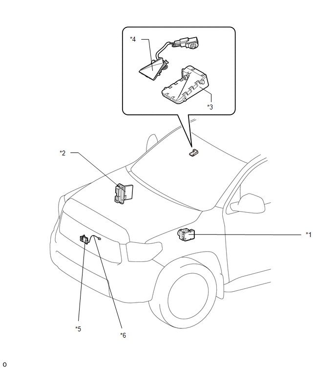
ILLUSTRATION 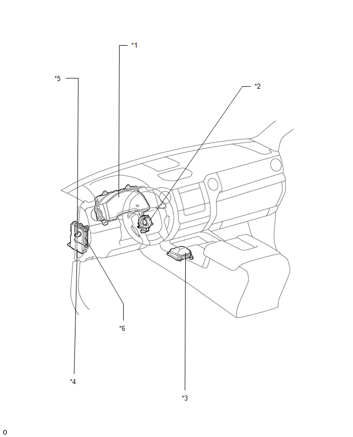
|
Toyota Tundra Service Manual > Power Tilt And Power Telescopic Steering Column System: Dtc Check / Clear
DTC CHECK / CLEAR 1. CHECK DTC (a) Turn the ignition switch off. (b) Connect the Techstream to the DLC3. (c) Turn the ignition switch to ON. (d) Turn the Techstream on. (e) Enter the following menus: Body Electrical / Tilt & Telescopic / Trouble Codes. (f) Read the DTCs. Click here 2. CLEAR DTC ...


