Toyota Tundra Service Manual: Power Source Circuit

DESCRIPTION

This circuit provides power to operate the forward recognition camera.

WIRING DIAGRAM

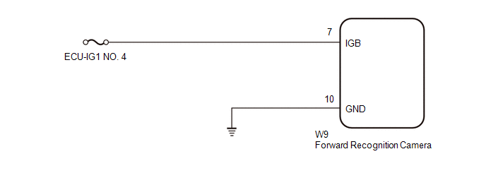
CAUTION / NOTICE / HINT

NOTICE:

Inspect the fuses for circuits related to this system before performing the following inspection procedure.

PROCEDURE

1.

CHECK HARNESS AND CONNECTOR (POWER SOURCE VOLTAGE)

(a) Disconnect the forward recognition camera connector.

*a

Front view of wire harness connector

(to Forward Recognition Camera)

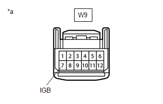
(b) Measure the voltage according to the value(s) in the table below.

Standard Voltage:

Tester Connection

Switch Condition

Specified Condition

W9-7 (IGB) - Body ground

Ignition switch ON

11 to 14 V

(c) Connect the forward recognition camera connector.

NG

REPAIR OR REPLACE HARNESS OR CONNECTOR

OK

2.

CHECK HARNESS AND CONNECTOR (FORWARD RECOGNITION CAMERA - BODY GROUND)

(a) Disconnect the forward recognition camera connector.

*a

Front view of wire harness connector

(to Forward Recognition Camera)

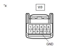
(b) Measure the resistance according to the value(s) in the table below.

Standard Resistance:

Tester Connection

Condition

Specified Condition

W9-10 (GND) - Body ground

Always

Below 1 Ω

(c) Connect the forward recognition camera connector

OK

PROCEED TO NEXT SUSPECTED AREA SHOWN IN PROBLEM SYMPTOMS TABLE

NG

REPAIR OR REPLACE HARNESS OR CONNECTOR

    Parts Location

    Precaution

    See More:

    Toyota Tundra Service Manual > Automatic Transmission System: Road Test
    ROAD TEST 1. PROBLEM SYMPTOM CONFIRMATION (a) Based on the result of the customer problem analysis, try to reproduce the symptoms. If the problem is that the transmission does not shift up or down, or that the shift point is too high or too low, conduct the following road test referring to the autom ...

    Toyota Tundra Owners Manual

    Toyota Tundra Service Manual

    © 2026 Copyright www.ttundra.com
    0.0332