PARTS LOCATION ILLUSTRATION 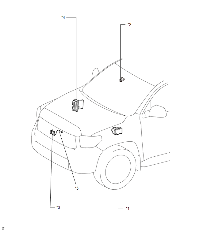
ILLUSTRATION 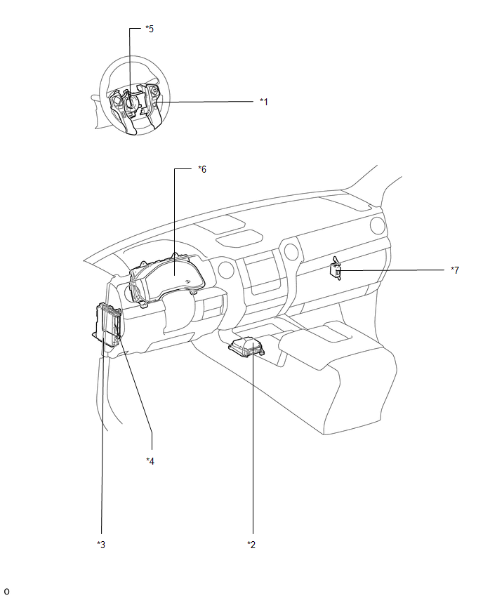
|
Toyota Tundra Service Manual > Seat Belt Warning System: System Diagram
SYSTEM DIAGRAM Communication Table Sender Receiver Signal Communication Method Center airbag sensor assembly Main body ECU (driver side junction block assembly) Front seat inner belt assembly LH buckle switch CAN Combination meter assembly Front seat inner belt assembly RH buckle switch Occupant det ...


