DISASSEMBLY PROCEDURE 1. INSPECT RUNOUT OF REAR DRIVE PINION COMPANION FLANGE SUB-ASSEMBLY
| (a) Using a dial indicator, measure the runout of the companion flange vertically and laterally. Text in Illustration
Maximum runout: |
Runout | Standard Condition | |
Vertical runout | 0.10 mm (0.00394 in.) | |
Lateral runout | 0.10 mm (0.00394 in.) |
If the runout is more than the maximum, replace the companion flange. |
|
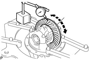
2. INSPECT RUNOUT OF DIFFERENTIAL RING GEAR
| (a) Using a dial indicator, measure the runout of the ring gear.
Maximum runout: 0.05 mm (0.00197 in.) If the runout is more than the maximum, replace the ring gear with a new one. |
|
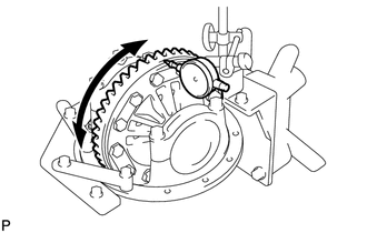
3. INSPECT DIFFERENTIAL RING GEAR BACKLASH
| (a) Using a dial indicator, measure the backlash of the ring gear.
Standard backlash: 0.10 to 0.20 mm (0.00394 to 0.00787 in.)
HINT: Measure at 3 or more positions around the circumference of the ring gear.
If the backlash is not within the specification, adjust or repair the side bearing preload as necessary. |
|
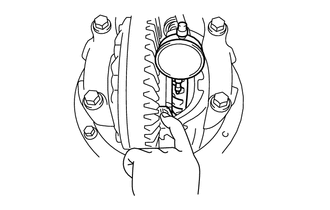
4. INSPECT DIFFERENTIAL SIDE GEAR BACKLASH
| (a) Using a dial indicator, measure the side gear backlash while holding one pinion gear toward the case.
Standard backlash: 0.15 mm (0.00591 in.) or less If the backlash is not within the specification, replace the side gear thrust washer with one of a different thickness. |
|
5. INSPECT DIFFERENTIAL DRIVE PINION PRELOAD
| (a) Using a torque wrench, measure the preload of the backlash between the drive pinion and ring gear.
Standard drive pinion preload (at starting): 1.62 to 2.25 N*m (17 to 22 kgf*cm, 15 to 19 in.*lbf)
If necessary, disassemble and inspect the differential. | |
6. INSPECT TOTAL PRELOAD |
(a) Using a torque wrench, measure the total preload with the teeth of the drive pinion and ring gear in contact.
Standard total preload (at starting): Standard drive pinion preload plus 0.19 to 0.38 N*m (2 to 3 kgf*cm, 2 to 3 in.*lbf)
If necessary, disassemble and inspect the differential. | |
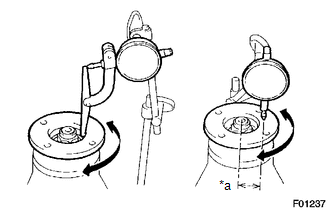
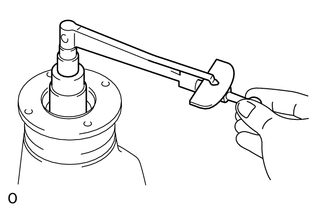
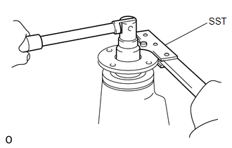
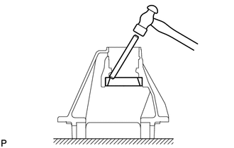
7. REMOVE REAR DRIVE PINION NUT
| (a) Using SST and a hammer, unstake the nut. SST: 09930-00010 |
|
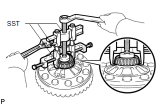
| (b) Using SST to hold the companion flange, remove the nut. SST: 09330-00021
09330-00030 | |
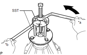
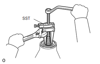
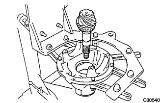
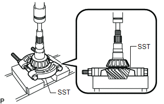
8. REMOVE REAR DRIVE PINION COMPANION FLANGE SUB-ASSEMBLY
| (a) Using SST, remove the companion flange. SST: 09950-30012
09951-03010 09953-03010 09954-03010 09956-03030
SST: 09955-03050 Text in Illustration |
|
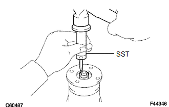
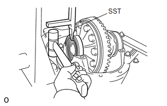
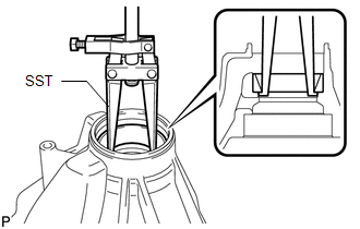
9. REMOVE REAR DIFFERENTIAL CARRIER OIL SEAL
| (a) Using SST, remove the oil seal. SST: 09308-10010 |
|
10. REMOVE REAR DIFFERENTIAL DRIVE PINION OIL SLINGER 11. REMOVE REAR DRIVE PINION FRONT BEARING
| (a) Using SST, remove the bearing (inner race). SST: 09950-40011
09951-04010 09953-04020 09952-04010 SST: 09955-04130
SST: 09958-04020 | |
(b) Remove the 2 preload adjusting shims. 12. REMOVE REAR DIFFERENTIAL CASE ASSEMBLY
| (a) Place matchmarks on the bearing cap and differential carrier. Text in Illustration |
|
(b) Remove the 4 bolts and 2 differential bearing caps.
| (c) Using SST and a plastic-faced hammer, remove the 2 plate washers.
SST: 09504-22012 HINT: Measure the plate washer thickness and note it down. |
|
(d) Remove the differential case with the bearing outer races from the carrier.
HINT: Tag the bearing outer races to show the location for reassembling.
13. REMOVE REAR DIFFERENTIAL DRIVE PINION
| (a) Remove the differential drive pinion and bearing spacer from the differential carrier. |
|
14. REMOVE REAR DRIVE PINION REAR BEARING
| (a) Using SST and a press, press out the bearing (inner race).
SST: 09950-00020 If either the drive pinion or ring gear is damaged, replace them as a set. |
|
15. REMOVE REAR DIFFERENTIAL DRIVE PINION PLATE WASHER 16. REMOVE REAR DRIVE PINION FRONT BEARING
| (a) Using SST, remove the bearing (outer race). SST: 09308-00010
If the bearing is damaged during removal, replace it. | |
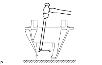
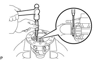
17. REMOVE DIFFERENTIAL OIL STORAGE RING
| (a) Using a brass bar and hammer, tap out the storage ring. |
|
18. REMOVE REAR DRIVE PINION REAR BEARING
| (a) Using a brass bar and hammer, tap out the bearing (outer race).
If the bearing is damaged during removal, replace it. | |
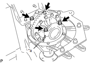
19. REMOVE DIFFERENTIAL RING GEAR
| (a) Place matchmarks on the ring gear and differential case. Text in Illustration |
|
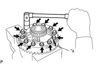
(b) Remove the 12 ring gear set bolts. (c) Using a plastic-faced hammer, tap on the ring gear to separate it from the differential case.
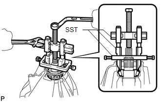
20. REMOVE REAR DIFFERENTIAL CASE BEARING
| (a) Using SST, remove the 2 bearings. SST: 09950-40011
09951-04010 09952-04010 09953-04020 09954-04010
09957-04010 09958-04011 SST: 09950-60010 09951-00500
SST: 09955-04120 HINT: Fix the claws of SST to the notches in the differential case. |
|
21. DISASSEMBLE DIFFERENTIAL CASE
| (a) Using a pin punch and hammer, tap out the straight pin. |
|
(b) Remove the pinion shaft, 2 pinion gears, 2 pinion gear thrust washers, 2 side gears and 2 side gear thrust washers. |