Toyota Tundra Service Manual: Inspection

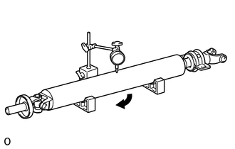
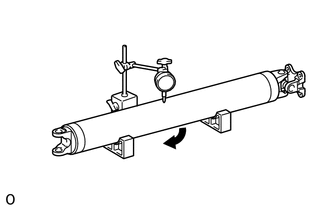
INSPECTION

CAUTION / NOTICE / HINT

PROCEDURE

1. INSPECT PROPELLER SHAFT WITH CENTER BEARING ASSEMBLY

(a) Using a dial indicator, measure the intermediate shaft runout.

Maximum runout:

0.61 mm (0.0240 in.)

If the intermediate shaft runout is more than the maximum, replace the propeller shaft with center bearing assembly.

(b) Using a dial indicator, measure the propeller shaft runout.

Maximum runout:

1.02 mm (0.0402 in.)

If the propeller shaft runout is more than the maximum, replace the propeller shaft with center bearing assembly.

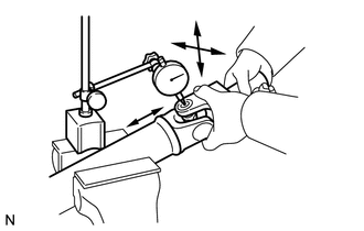
2. INSPECT PROPELLER SHAFT UNIVERSAL JOINT SPIDER BEARING

(a) Mount the propeller shaft in a vise.

NOTICE:

Be careful not to grip the propeller shaft tube too tightly in a vise as this will cause deformation.

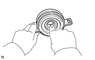
(b) Inspect the spider bearing for wear or damage.

(c) Using a dial indicator, measure the spider bearing axial play by turning the yoke of the flange while holding the shaft tightly.

Maximum bearing axial play:

0.05 mm (0.00197 in.)

If the spider bearing axial play is more than the maximum, replace the spider bearing.

3. INSPECT NO. 1 CENTER SUPPORT BEARING ASSEMBLY

(a) Check that the bearing turns freely.

If the bearing is damaged, worn, or does not turn freely, replace it.

    Disassembly

    Installation

    See More:

    Toyota Tundra Service Manual > Rear View Monitor System(for Navigation Receiver Type): Open or Short Circuit in Back Camera Signal (C1622)
    DESCRIPTION This DTC is stored if the navigation receiver assembly judges as a result of its self check that the signals or signal lines between the navigation receiver assembly and the television camera assembly are not normal. DTC Code DTC Detection Condition Trouble Area C1622 Open or Short Circu ...

    Toyota Tundra Owners Manual

    Toyota Tundra Service Manual

    © 2025 Copyright www.ttundra.com
    0.0358