Components COMPONENTS ILLUSTRATION 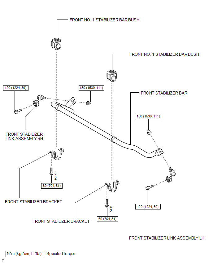 Inspection INSPECTION PROCEDURE 1. INSPECT FRONT STABILIZER LINK ASSEMBLY LH 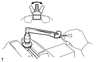 (a) Temporarily install the nut, and flip the ball joint stud back and forth 5 times as shown in the illustration. (b) Use a torque wrench to turn the nut continuously at a rate of 2 to 3 seconds per turn. Take the torque reading on the fifth turn. Torque: Standard turning torque : 0.5-3.4 N·m {5.1-36 kgf·cm, 4.4-30 in·lbf}
(c) Check the dust boot for cracks or grease leakage. Installation INSTALLATION PROCEDURE 1. INSTALL FRONT NO. 1 STABILIZER BAR BUSH 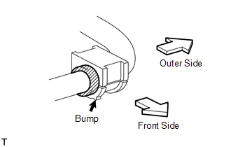 (a) Install the 2 bushes to the outer side of the bush stoppers on the front stabilizer bar as shown in the illustration. NOTICE: Be sure to install the front No. 1 stabilizer bar bushes so that the cut and bump of each bush faces the front of the vehicle. 2. TEMPORARILY INSTALL FRONT STABILIZER BAR (a) Temporarily install the front stabilizer bar with the 4 bolts and the stabilizer bracket LH and RH. 3. TIGHTEN FRONT STABILIZER BRACKET  (a) Tighten the 4 bolts. Torque: 69 N·m {704 kgf·cm, 51 ft·lbf} 4. TEMPORARILY INSTALL FRONT STABILIZER LINK ASSEMBLY LH 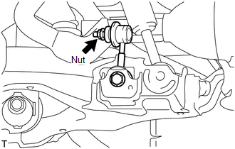 (a) Temporarily install the stabilizer link with the nut and bolt. (b) Tighten the nut. Torque: 150 N·m {1530 kgf·cm, 111 ft·lbf} 5. TEMPORARILY INSTALL FRONT STABILIZER LINK ASSEMBLY RH HINT: Use the same procedures described for the LH side. 6. STABILIZE SUSPENSION 7. TIGHTEN FRONT STABILIZER LINK ASSEMBLY LH 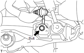 (a) Tighten the bolt. Torque: 120 N·m {1224 kgf·cm, 89 ft·lbf} 8. TIGHTEN FRONT STABILIZER LINK ASSEMBLY RH HINT: Use the same procedures described for the LH side. 9. INSTALL FRONT WHEEL Torque: for Aluminum Wheel : 131 N·m {1336 kgf·cm, 97 ft·lbf} for Steel Wheel : 209 N·m {2131 kgf·cm, 154 ft·lbf} Removal REMOVAL PROCEDURE 1. REMOVE FRONT WHEEL 2. REMOVE FRONT STABILIZER LINK ASSEMBLY LH 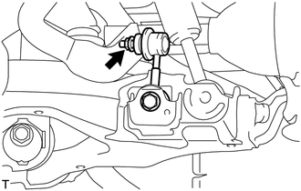 (a) Remove the bolt, nut and stabilizer link. HINT: If the ball joint turns together with the nut, use a 6 mm hexagon wrench to hold the stud. 3. REMOVE FRONT STABILIZER LINK ASSEMBLY RH HINT: Use the same procedures described for the LH side. 4. REMOVE FRONT STABILIZER BRACKET 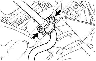 (a) Remove the 4 bolts and 2 brackets. 5. REMOVE FRONT STABILIZER BAR (a) Remove the front stabilizer bar from the vehicle. (b) Remove the 2 brackets and cushions from the stabilizer bar. 6. REMOVE FRONT NO. 1 STABILIZER BAR BUSH (a) Remove the 2 bushes from the front stabilizer bar. |
Toyota Tundra Service Manual > Cruise Control System: Brake Switch "A" Circuit (P0571)
DESCRIPTION When the brake pedal is depressed, the stop light switch assembly sends a signal to the ECM. Upon receiving the signal, the ECM cancels the cruise control system. DTC No. Detection Item DTC Detection Condition Trouble Area P0571 Brake Switch "A" Circuit When voltage of STP terminal and t ...


