REMOVAL CAUTION / NOTICE / HINT HINT:
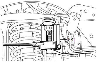
PROCEDURE 1. REMOVE FRONT WHEEL 2. REMOVE FRONT SHOCK ABSORBER WITH COIL SPRING LH (a) Remove the front shock absorber with coil spring (see page
3. DISCONNECT SKID CONTROL SENSOR WIRE 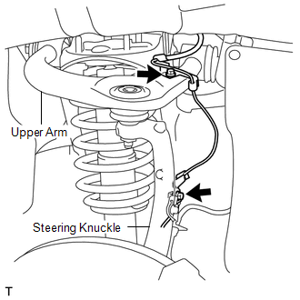 (a) Remove the 2 bolts and disconnect the sensor wire from the steering knuckle and suspension upper arm. 4. DISCONNECT STEERING KNUCKLE LH (a) Support the front suspension lower arm LH with a jack. (b) Remove the clip and the nut.
5. REMOVE FRONT FENDER APRON SEAL LH 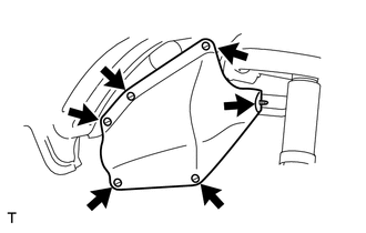 (a) Using a clip remover, remove the 6 clips and apron seal. 6. REMOVE FRONT FENDER APRON SEAL REAR LH 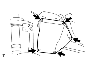 (a) Using a clip remover, remove the 5 clips and apron seal. 7. REMOVE FRONT SUSPENSION UPPER ARM ASSEMBLY 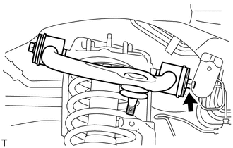 (a) Remove the nut, bolt, 2 washers and suspension upper arm. |
Toyota Tundra Service Manual > Sfi System: Oxygen Sensor Circuit (Bank 1 Sensor 2) (P0136-P0139,P013A,P013C,P0156-P0159)
DESCRIPTION In order to obtain a high purification rate of the carbon monoxide (CO), hydrocarbon (HC) and nitrogen oxide (NOx) components in the exhaust gas, a TWC is used. For the most efficient use of the TWC, the air-fuel ratio must be precisely controlled so that it is always close to the stoich ...

 ).
).