Components COMPONENTS ILLUSTRATION 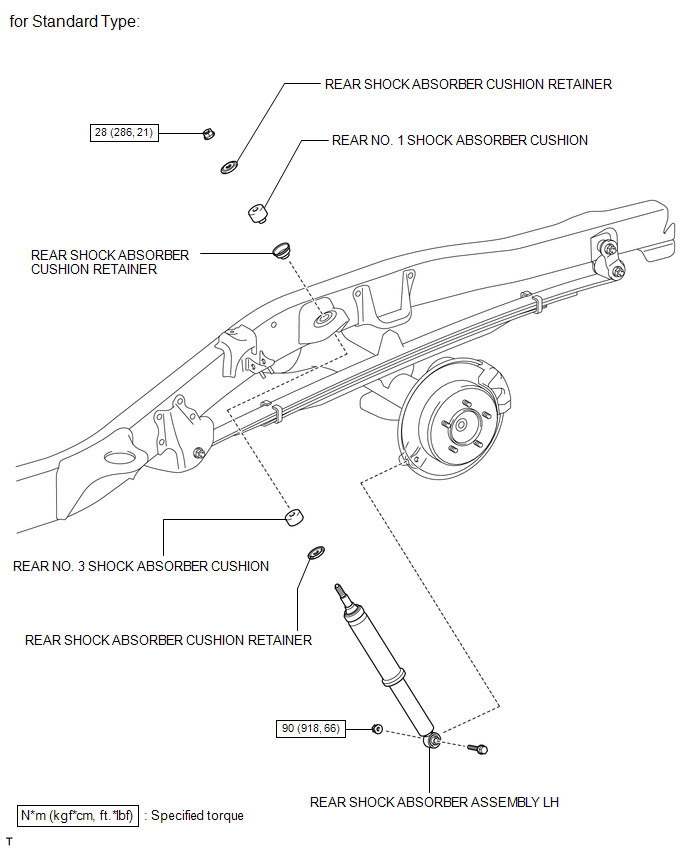 ILLUSTRATION 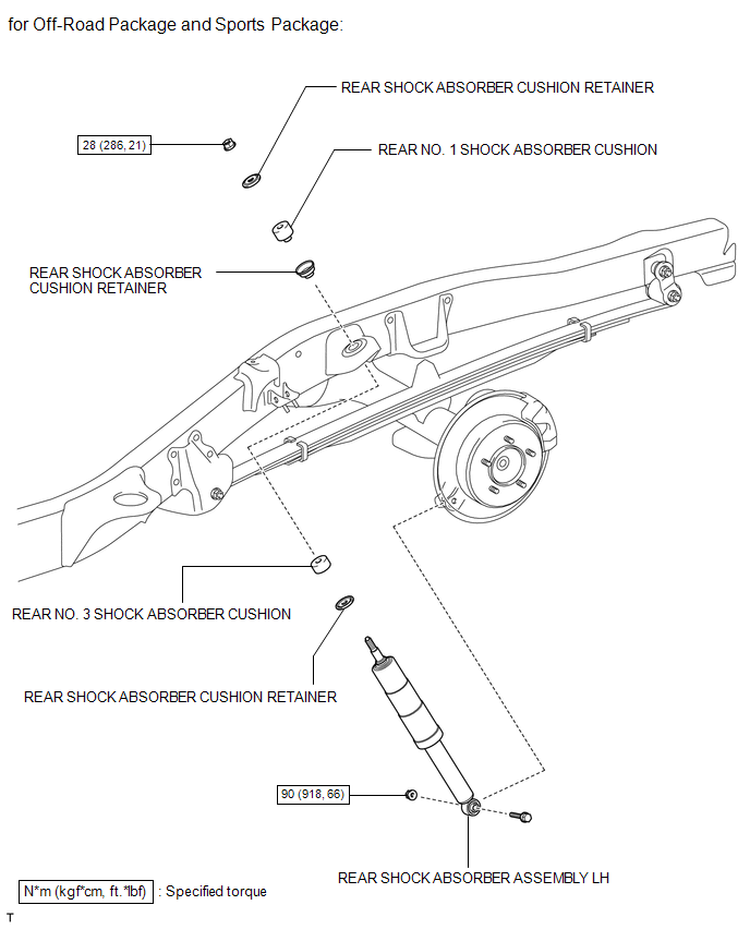 Disposal DISPOSAL PROCEDURE 1. DISPOSE OF SHOCK ABSORBER ASSEMBLY REAR 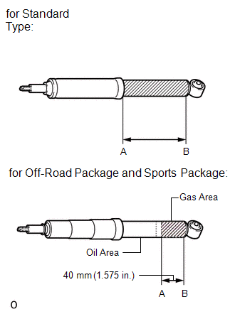 (a) Fully extend the rear shock absorber rod. (b) Using a drill, make a hole in the cylinder between A and B shown in the illustration to discharge the gas inside. CAUTION: Be careful when drilling because shards of metal may fly about. Always use the proper safety equipment. NOTICE: The gas is colorless, odorless and nonpoisonous. Inspection INSPECTION PROCEDURE 1. INSPECT REAR SHOCK ABSORBER ASSEMBLY LH 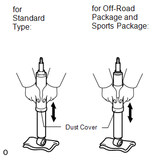 (a) Compress and extend the shock absorber rod 4 times or more. Check that there is no abnormal resistance or unusual sound during the operation. If there is any abnormality, replace the shock absorber assembly with a new one. NOTICE:
Installation INSTALLATION CAUTION / NOTICE / HINT HINT:
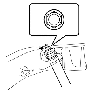
PROCEDURE 1. TEMPORARILY INSTALL REAR SHOCK ABSORBER ASSEMBLY LH (a) Install the 2 retainers and No. 3 cushion to the shock absorber.
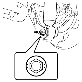
2. STABILIZE SUSPENSION (a) Lower the vehicle. (b) Press down on the vehicle several times to stabilize the suspension. 3. TIGHTEN REAR SHOCK ABSORBER ASSEMBLY LH (a) Tighten the bolt and 2 nuts. Torque: Upper side : 28 N·m {286 kgf·cm, 21 ft·lbf} Lower side : 90 N·m {918 kgf·cm, 66 ft·lbf} 4. INSTALL REAR WHEEL Torque: for Aluminum Wheel : 131 N·m {1336 kgf·cm, 97 ft·lbf} for Steel Wheel : 209 N·m {2131 kgf·cm, 154 ft·lbf} 5. REMOVE SAFETY STANDS Removal REMOVAL CAUTION / NOTICE / HINT HINT:
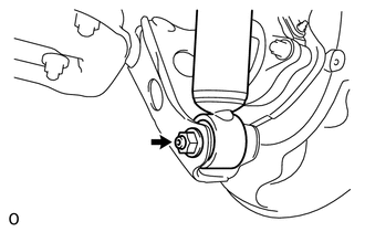
PROCEDURE 1. SUPPORT BODY WITH SAFETY STANDS (a) Jack up and support the body on safety stands. (b) Lower the axle housing until the leaf spring tension is free, and keep it at this position. 2. REMOVE REAR WHEEL 3. REMOVE REAR SHOCK ABSORBER ASSEMBLY LH 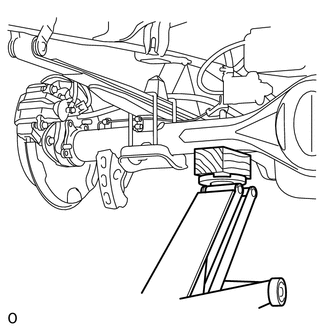 (a) Support the rear axle housing with a jack using a wooden block to avoid damage.
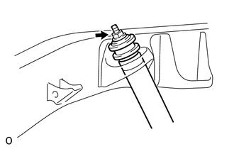
(d) Remove the 2 retainers and No. 3 cushion from the shock absorber. |
Toyota Tundra Service Manual > Rear Door(for Double Cab): On-vehicle Inspection
ON-VEHICLE INSPECTION PROCEDURE 1. INSPECT REAR DOOR PANEL SUB-ASSEMBLY LH (a) Check that the clearance measurements of areas A to J are within the standard range. Standard measurement: Area Specified Condition Area Specified Condition A 4.7 to 7.7 mm (0.185 to 0.303 in.) F 2.5 to 5.5 mm (0.0984 to ...

 ).
).
 ).
).