Toyota Tundra Service Manual: How To Proceed With Troubleshooting

HOW TO PROCEED WITH TROUBLESHOOTING

1. OPERATION FLOW

HINT:

Perform troubleshooting in accordance with the procedures below. The following is an outline of basic troubleshooting procedures. Confirm the troubleshooting procedures for the circuit you are working on before beginning troubleshooting.

2. 1.VEHICLE BROUGHT TO WORKSHOP

3. 2.CUSTOMER PROBLEM ANALYSIS

(a) Ask the customer about the conditions and environment when the problem occurred.

4. 3.INSPECT BATTERY VOLTAGE

Standard voltage:

11 to 14 V

If the voltage is below 11 V, recharge or replace the battery before proceeding.

5. 4.SYMPTOM CONFIRMATION AND DTC (INCLUDING FREEZE FRAME DATA) CHECK

(a) Visually check the wire harnesses, connectors and fuses for open and short circuits.

(b) Warm up the engine to the normal operating temperature.

(c) Confirm the problem symptoms and conditions, and check for DTCs.

Result

Result

Proceed to

DTC is output

Go to step 5

DTC is not output

Go to step 6

Result

Proceed to

Go to step 7

6. 5.DTC CHART

(a) Check the results obtained in the DTC check. Then find the output DTC in the DTC chart. Look at the "Trouble Area" column for a list of potentially malfunctioning circuits and / or parts.

7. 6.PROBLEM SYMPTOMS TABLE

(a) Check the results obtained in the symptom confirmation. Then find the problem symptoms in the problem symptoms table. Look at the "Suspected Area" column for a list of potentially malfunctioning circuits and / or parts.

8. 7.CIRCUIT INSPECTION OR PARTS INSPECTION

(a) Confirm the malfunctioning circuit or part.

9. 8.ADJUST, REPAIR OR REPLACE

(a) Adjust, repair or replace the malfunctioning circuit or parts.

10. 9.CONFIRMATION TEST

(a) After the adjustment, repairs or replacement, confirm that the malfunction no longer exists. If the malfunction does not reoccur, perform a confirmation test under the same conditions and in the same environment as when the malfunction occurred the first time.

(b) END

11. CUSTOMER PROBLEM ANALYSIS

HINT:

  • In troubleshooting, confirm that the problem symptoms have been accurately identified. Preconceptions should be discarded in order to make an accurate judgment. To clearly understand what the problem symptoms are, it is extremely important to ask the customer about the problem and the conditions at the time the malfunction occurred.
  • Gather as much information as possible for reference. Past problems that seem unrelated may also help in some cases.
  • The following 5 questions are important points in the problem analysis:

    What

    Vehicle model, system name

    When

    Date, time, occurrence frequency

    Where

    Road conditions

    Under what conditions?

    Running conditions, driving conditions, weather conditions

    How did it happen?

    Problem symptoms

12. SYMPTOM CONFIRMATION AND DIAGNOSTIC TROUBLE CODE

HINT:

The diagnostic system in the TOYOTA TUNDRA has various functions.

  • The first function is the Diagnostic Trouble Code (DTC) check. A DTC is a code stored in the ECU memory whenever a malfunction in the signal circuits to the ECU occurs. In a DTC check, a previous malfunction's DTC can be checked by a technician during troubleshooting.
  • Another function is the Input Signal Check, which checks if the signals from various switches are sent to the ECU correctly.

    By using these functions, the problem areas can be narrowed down and troubleshooting is more effective. Diagnostic functions are incorporated in the following systems in the TOYOTA TUNDRA.

    System

    DTC Check

    (Normal Mode)

    DTC Check

    (Check Mode)

    Freeze Frame Data

    Sensor Check / Test Mode (Input Signal Check)

    Data List

    Active Test

    Customize Parameter

    SFI System (for 1UR-FE)

    -

    -

    SFI System (for 3UR-FE)

    -

    -

    SFI System (for 3UR-FBE)

    -

    -

    Cruise Control System

    -

    -

    -

    Dynamic Radar Cruise Control System

    -

    -

    -

    Forward Recognition Camera System

    -

    -

    -

    Lane Departure Alert System

    -

    -

    Automatic Transmission System (for A760E)

    -

    -

    Automatic Transmission System (for A760F)

    -

    -

    Automatic Transmission System (for AB60E)

    -

    -

    Automatic Transmission System (for AB60F)

    -

    -

    Tire Pressure Warning System

    -

    -

    -

    Touch Select 2-4 and High-low System

    -

    -

    -

    -

    -

    -

    Vehicle Stability Control System

    -

    -

    Trailer Brake Control System

    -

    -

    -

    Power Tilt and Power Telescopic Steering Column System

    -

    -

    Air Conditioning System (for Automatic Air Conditioning System)

    -

    -

    -

    Air Conditioning System (for Manual Air Conditioning System)

    -

    -

    -

    -

    Airbag System

    -

    -

    -

    -

    Occupant Classification System

    -

    -

    -

    -

    -

    Seat Belt Warning System

    -

    -

    -

    -

    -

    Theft Deterrent System

    -

    -

    -

    -

    Engine Immobiliser System

    -

    -

    -

    -

    Lighting System

    -

    -

    -

    Wiper and Washer System

    -

    -

    -

    -

    -

    -

    Power Door Lock Control System

    -

    -

    -

    -

    Wireless Door Lock Control System

    -

    -

    -

    -

    Key Reminder Warning System

    -

    -

    -

    -

    -

    Meter / Gauge System

    -

    -

    -

    Audio and Visual System

    -

    -

    -

    -

    Navigation System

    -

    -

    -

    -

    Blind Spot Monitor System

    -

    -

    -

    Rear View Monitor System (for Radio and Display Type)

    -

    -

    -

    -

    -

    -

    Rear View Monitor System (for Navigation Receiver Type)

    -

    -

    -

    -

    -

    -

    Pre-collision System

    -

    -

    Power Window Control System (w/ Jam Protection Function)

    -

    -

    -

    Power Window Control System (w/o Jam Protection Function)

    -

    -

    -

    -

    -

    Windshield Deicer System

    -

    -

    -

    -

    -

    -

    Window Defogger System

    -

    -

    -

    -

    -

    -

    Power Mirror Control System (w/ Memory)

    -

    -

    -

    -

    Power Seat Control System (w/ Memory)

    -

    -

    -

    Sliding Roof System

    -

    -

    -

    CAN Communication System

    -

    -

    -

    -

    -

    LIN Communication System

    -

    -

    -

    -

    -

  • In the DTC check, it is very important to determine whether the problem indicated by the DTC is either: 1) still occurring; or 2) occurred in the past but has since returned to normal. In addition, the DTC should be compared to the problem symptom to see if they are related. For this reason, DTCs should be checked before and after confirmation of symptoms (i.e., whether or not problem symptoms exist) to determine current system conditions, as shown in the flowchart below.
  • Never skip the DTC check. Failing to check DTCs may, depending on the case, result in unnecessary troubleshooting for systems operating normally or lead to repairs not related to the problem. Follow the procedures listed in the flowchart in the correct order.
  • The following flowchart shows how to proceed with troubleshooting using the DTC check. Directions from the flowchart will indicate how to proceed either to DTC troubleshooting or to the troubleshooting of each problem symptom.

13. 1.DTC CHECK

14. 2.MAKE A NOTE OF DTCS DISPLAYED AND THEN CLEAR MEMORY

15. 3.SYMPTOM CONFIRMATION

Result

Result

Proceed to

No symptoms exist

Go to step 4

Symptoms exist

Go to step 5

16. 4.SIMULATION TEST USING SYMPTOM SIMULATION METHODS

17. 5.DTC CHECK

Result

Result

Proceed to

DTC is not output

Go to step 6

DTC is output

TROUBLESHOOTING OF PROBLEM INDICATED BY DTC

18. 6.SYMPTOM CONFIRMATION

Result

Result

Proceed to

Symptoms exist

TROUBLESHOOTING OF EACH PROBLEM SYMPTOM

No symptoms exist

SYSTEM NORMAL

If a DTC was displayed in the initial DTC check, the problem may have occurred in a wire harness or connector in that circuit in the past. Check the wire harness and connectors.

The problem is still occurring in a place other than the diagnostic circuit (the DTC displayed first is either for a past problem or a secondary problem).

19. SYMPTOM SIMULATION

HINT:

The most difficult case in troubleshooting is when no problem symptoms occur. In such a case, a thorough problem analysis must be carried out. A simulation of the same or similar conditions and environment in which the problem occurred in the customer's vehicle should be carried out. No matter how much skill or experience a technician has, troubleshooting without confirming the problem symptoms will lead to important repairs being overlooked and mistakes or delays.

For example:

With a problem that only occurs when the engine is cold or as a result of vibration caused by the road during driving, the problem can never be determined if the symptoms are being checked on a stationary vehicle or on a vehicle with a warmed-up engine. Vibration, heat or water penetration (moisture) is difficult to reproduce. The symptom simulation tests below are effective substitutes for the conditions and can be applied on a stationary vehicle.

Important points in the symptom simulation test:

In the symptom simulation test, the problem symptoms as well as the problem area or parts must be confirmed. First, narrow down the possible problem circuits according to the symptoms. Then, connect the tester and carry out the symptom simulation test, judging whether the circuit being tested is defective or normal. Also, confirm the problem symptoms at the same time. Refer to the problem symptoms table for each system to narrow down the possible causes.

To reproduce DTCs, it is necessary to satisfy the respective DTC detection conditions.

(a) VIBRATION METHOD:

When a malfunction seems to occur as a result of vibration.

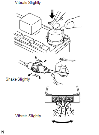
(1) PART AND SENSOR

Apply slight vibration with a finger to the part of the sensor suspected to be the cause of the problem, and check whether or not the malfunction occurs.

NOTICE:

Applying strong vibration to relays may open them.

(2) CONNECTORS

Slightly shake the connector vertically and horizontally.

(3) WIRE HARNESS

Slightly shake the wire harness vertically and horizontally.

HINT:

The connector joint and fulcrum of the vibration are the major areas that should be checked thoroughly.

(b) HEAT METHOD:

When a malfunction seems to occur when the area in question is heated.

(1) Heat the component that is the possible cause of the malfunction with a hair dryer or similar device. Check if the malfunction occurs.

NOTICE:

  • Do not heat to more than 60°C (140°F). Exceeding this temperature may damage components.
  • Do not apply heat directly to the parts in the ECU.

(c) WATER SPRINKLING METHOD:

When a malfunction seems to occur on a rainy day or in high-humidity.

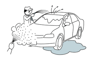
(1) Sprinkle water onto the vehicle and check if the malfunction occurs.

NOTICE:

  • Never sprinkle water directly into the engine compartment. Indirectly change the temperature and humidity by spraying water onto the front of the radiator.
  • Never apply water directly onto the electronic components.

HINT:

If the vehicle has or had a water leakage problem, the leakage may have damaged the ECU or connections. Look for evidence of corrosion or short circuits. Proceed with caution during water tests.

(d) HIGH ELECTRICAL LOAD METHOD:

When a malfunction seems to occur when the electrical load is excessive.

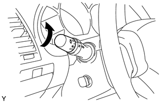
(1) Turn on the heater blower, headlights, rear window defogger and all other electrical loads. Check if the malfunction reoccurs.

20. DIAGNOSTIC TROUBLE CODE CHART

Look for output Diagnostic Trouble Codes (DTCs) (from the DTC checks) in the appropriate section's Diagnostic Trouble Code Chart. Use the chart to determine the trouble area and the proper inspection procedure. A description of each of the chart's columns is below.

Item

Description

DTC Code

Indicates the diagnostic trouble code.

Detection Item

Indicates the system or details of the problem.

Trouble Area

Indicates the suspected areas of the problem.

See Page

Indicates the page where the inspection procedures for each circuit can be found, or where there are instructions for checks and repairs.

21. PROBLEM SYMPTOMS TABLE

When a "Normal" code is output during a DTC check but the problem is still occurring, use the Problem Symptoms Table. The suspected areas (circuits or parts) for each problem symptom are in the table. The suspected areas are listed in order of probability. A description of each of the chart's columns is below.

HINT:

In some cases, the problem is not detected by the diagnostic system even though a problem symptom is present. It is possible that the problem is occurring outside the detection range of the diagnostic system, or that the problem is occurring in a completely different system.

Item

Description

Symptom

-

Suspected Area

Indicates the circuit or part which needs to be checked.

See Page

Indicates the page where the flowchart for each circuit is located.

22. CIRCUIT INSPECTION

A description of the main areas of each circuit inspection is below.

Item

Description

Circuit Description

The major role and operation of the circuit and its component parts are explained.

DTC Code, DTC Detection Condition, Trouble Area

Indicates the diagnostic trouble codes, diagnostic trouble code detection conditions, and trouble areas of a problem.

Wiring Diagram

This shows a wiring diagram of the circuit.

Use this diagram together with an ELECTRICAL WIRING DIAGRAM to thoroughly understand the circuit.

Inspection Procedures

Use the inspection procedures to determine if the circuit is normal or abnormal. If abnormal, use the inspection procedures to determine whether the problem is located in the sensors, actuators, wire harnesses or ECU.

Inspection Procedure Connector Illustrations

  • Connector being checked is connected:

    Connections of tester are indicated by (+) or (-) after the terminal name.

  • Connector being checked is disconnected:

    For illustrations of inspections between a connector and body ground, information about the body ground is not shown in the illustration.

    General Information

    Electronic Circuit Inspection Procedure

    See More:

    Toyota Tundra Service Manual > Sfi System: Mass Air Flow Circuit Low (P0102,P0103)
    DESCRIPTION The Mass Air Flow (MAF) meter is a sensor that measures the amount of air flowing through the throttle valve. The ECM uses this information to determine the fuel injection time and to provide the appropriate air-fuel ratio. Inside the MAF meter, there is a heated platinum wire which is e ...

    Toyota Tundra Owners Manual

    Toyota Tundra Service Manual

    © 2024 Copyright www.ttundra.com
    0.0129