REASSEMBLY CAUTION / NOTICE / HINT
HINT: Coat all of the sliding and rotating surfaces with Toyota Genuine Transfer gear oil LF 75W or equivalent before reassembly. PROCEDURE
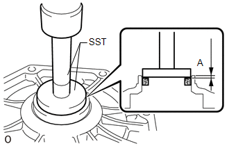
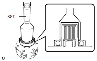
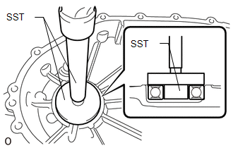
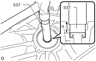
1. INSTALL TRANSFER CASE OIL SEAL
| (a) Using SST and a hammer, tap in a new transfer case oil seal as shown in the illustration.
SST: 09950-60010 09951-00630 SST: 09950-70010 09951-07100
Drive in depth (A): 1.4 to 2.4 mm (0.056 to 0.094 in.) NOTICE:
Be careful not to damage or deform the transfer case oil seal. |
|
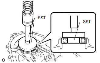
2. INSTALL TRANSFER DRIVEN SPROCKET BEARING (FRONT)
| (a) Using SST and a press, press in a new transfer driven sprocket bearing (front) as shown in the illustration.
SST: 09950-60010 09951-00390 09952-06010 SST: 09950-60020
09951-00910 SST: 09950-70010 09951-07100 NOTICE:
The transfer driven sprocket bearing (front) should be installed completely. |
|
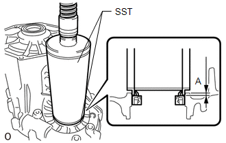
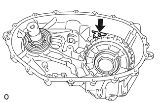
3. INSTALL NO. 2 TRANSFER CASE OIL SEAL
| (a) Using SST and a press, press in a new No. 2 transfer case oil seal as shown in the illustration.
SST: 09316-12010 SST: 09513-36040 Drive in depth (A):
1.5 to 2.5 mm (0.060 to 0.098 in.) NOTICE: Be careful not to damage or deform the No. 2 transfer case oil seal. |
|
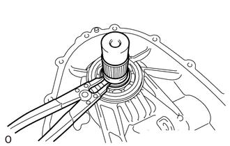
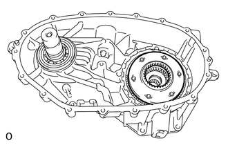
4. INSTALL OUTPUT SHAFT COMPANION FLANGE SUB-ASSEMBLY (FRONT)
| (a) Install the output shaft companion flange sub-assembly (front). |
|
(b) Using a snap ring expander, install the shaft snap ring. 5. INSTALL TRANSFER OIL SEPARATOR
| (a) Using a T25 ''TORX'' socket wrench, install the bolt and transfer oil separator.
Torque: 7.6 N·m {77 kgf·cm, 67 in·lbf} | |
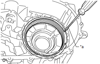
6. INSPECT TRANSFER LOWER PLANETARY RING GEAR
| (a) Install the transfer lower planetary ring gear. | |
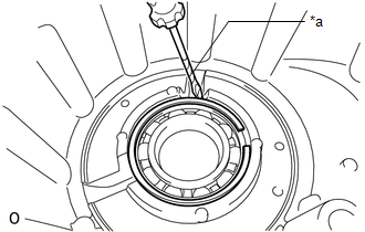
(b) Using a screwdriver, install the transfer lower planetary ring gear hole snap ring. Text in Illustration
HINT: Tape the screwdriver tip before use. 7. INSTALL TRANSFER LOWER PLANETARY GEAR ASSEMBLY
| (a) Using SST and a press, press in a new transfer input gear radial ball bearing.
SST: 09214-76011 NOTICE: The transfer input gear radial ball bearing should be installed completely. |
|
| (b) Install the transfer lower planetary gear assembly. |
|
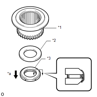
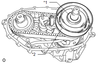
8. INSTALL TRANSFER HIGH AND LOW CLUTCH SLEEVE
| (a)
Install the transfer lower planetary gear bearing, the No. 2 transfer
output shaft spacer and the transfer high and low clutch sleeve. Text in Illustration |
*1 | Transfer High and Low Clutch Sleeve | |
*2 | No. 2 Transfer Output Shaft Spacer | |
*3 | Transfer Lower Planetary Gear Bearing | |
*a | Transfer Lower Planetary Gear Assembly Side |
NOTICE: Make sure that the transfer lower planetary gear bearing is installed facing the correct direction. |
|
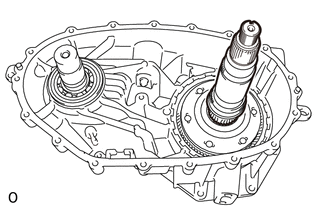
9. INSTALL REAR TRANSFER OUTPUT SHAFT
| (a) Install the rear transfer output shaft. | |
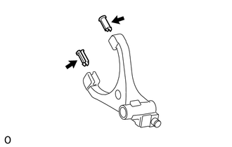
10. INSTALL NO. 1 TRANSFER GEAR SHIFT FORK
| (a) Install the 2 gear shift fork pads to the No. 1 transfer gear shift fork. |
|
| (b) Install the No. 1 transfer gear shift fork. | |
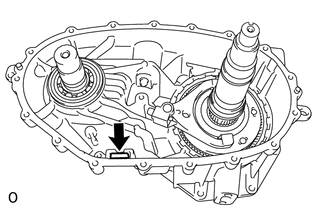
11. INSTALL TRANSFER CASE MAGNET
| (a) Install the transfer case magnet. | |
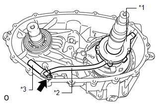
12. INSTALL TRANSFER OIL PUMP BODY SUB-ASSEMBLY
| (a) Install the transfer oil strainer sub-assembly to the transfer oil tube. |
|
(b) Install the transfer oil tube to the transfer oil pump body sub-assembly.
(c) Install the transfer oil pump body sub-assembly together with the transfer oil tube and transfer oil strainer sub-assembly. Text in Illustration |
*1 | Transfer Oil Pump Body Sub-assembly | |
*2 | Transfer Oil Tube | |
*3 | Transfer Oil Strainer Sub-assembly |
(d) Using a T25 ''TORX'' socket wrench, install the bolt. Torque:
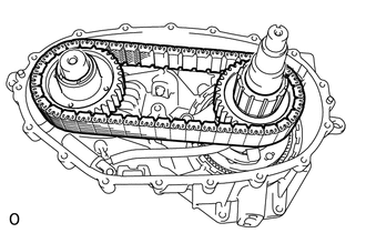
7.6 N·m {77 kgf·cm, 67 in·lbf} 13. INSTALL TRANSFER DRIVE SPROCKET SUB-ASSEMBLY
| (a) Install the transfer drive sprocket sub-assembly and transfer driven sprocket to the front transfer drive chain. |
|
(b) Install the transfer drive sprocket sub-assembly together with the front transfer drive chain and transfer driven sprocket.
NOTICE: Do not drop the transfer drive sprocket sub-assembly, front transfer drive chain and transfer driven sprocket.
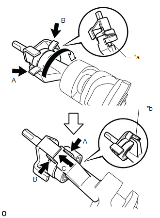
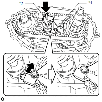
14. INSTALL CONTROL SELECT SHAFT SUB-ASSEMBLY (a) Install the control select shaft sub-assembly.
NOTICE: When
removing the rear transfer case, the spring of the control select shaft
sub-assembly may become detached. Check the condition of the spring
before installing the control select shaft sub-assembly, and if the
spring is not in the correct position, correct the spring as shown in
the illustration.
CAUTION:
- Wear protective gloves to avoid injuries to your hands.
- Take care when performing this procedure as the spring is under high tension.
| (1)
Make sure the spring is positioned as indicated by arrows A and B, and
then rotate the control select shaft in the direction indicated by the
arrow shown in the illustration. | |
(2) Rotate the control select shaft until the part of the spring indicated by arrow A moves past the part indicated by arrow B.
(3)
Slide the control select shaft in the direction indicated by arrow C in
the illustration to return the spring to the correct position. Text in Illustration |
*a | Part of the Spring Shown by Arrow A in the Open Position | |
*b | Control Select Shaft Sub-assembly in Correct Position |
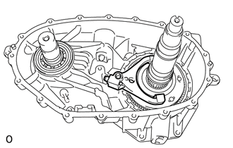
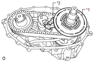
| (b)
Install the No. 1 transfer gear shift fork to the side of the control
select shaft sub-assembly as shown in the illustration. Text in Illustration |
*1 | No. 1 Transfer Gear Shift Fork | |
*2 | Control Select Shaft Sub-assembly | |
|
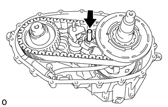
15. INSTALL SOLENOID LOCK PLATE WITH NO. 2 TRANSFER GEAR SHIFT FORK
| (a) Install the No. 2 transfer gear shift fork to the solenoid lock plate. |
|
(b) Install the solenoid lock plate together with the No. 2 transfer gear shift fork. Text in Illustration |
*1 | Solenoid Lock Plate Assembly | |
*2 | No. 2 Transfer Gear Shift Fork Sub-assembly |
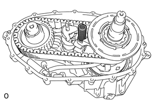
16. INSTALL TRANSFER HIGH AND LOW SHIFT FORK SHAFT
| (a) Install the transfer high and low shift fork shaft. |
|
17. INSTALL TRANSFER SELECT RETURN SPRING
| (a) Install the transfer select return spring. | |
18. INSTALL SOLENOID COVER
| (a) Install the solenoid cover and No. 1 transfer output shaft spacer. Text in Illustration |
*1 | No. 1 Transfer Output Shaft Spacer | |
*2 | Solenoid Cover | |
|
19. INSTALL REAR TRANSFER OUTPUT SHAFT RADIAL BALL BEARING
| (a) Install the rear transfer output shaft radial ball bearing. |
|
(b) Using a screwdriver, install the transfer output shaft rear shaft snap ring. Text in Illustration
HINT: Tape the screwdriver tip before use. 20. INSTALL TRANSFER DRIVEN SPROCKET BEARING (REAR)
| (a) Using SST and a hammer, tap in a new transfer driven sprocket bearing (rear).
SST: 09950-60010 09951-00340 09952-06010 SST: 09950-60020
09951-00730 SST: 09950-70010 09951-07150 NOTICE:
The transfer driven sprocket bearing (rear) should be installed completely. |
|
21. INSTALL TRANSFER COVER TYPE T OIL SEAL
| (a) Using SST and a hammer, tap in a new transfer cover type T oil seal.
SST: 09950-70010 09951-07100 SST: 09950-60010 09951-00190
Drive in depth (A): 14.4 to 15.4 mm (0.567 to 0.606 in.) |
|
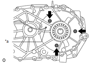
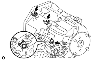
22. INSTALL SOLENOID COIL SUB-ASSEMBLY
| (a) Install the solenoid coil sub-assembly with the 3 nuts. Torque:
9.5 N·m {97 kgf·cm, 84 in·lbf} Text in Illustration |
*a | Rear Transfer Case Hole |
HINT: Make sure that the solenoid coil sub-assembly terminal extends out from the rear transfer case hole. |
|
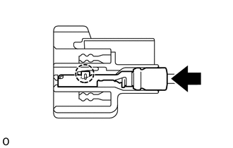
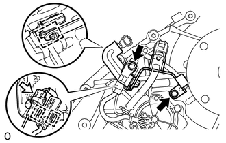
(b) Connect the solenoid coil sub-assembly terminal.
| (1) Attach the claw to connect the solenoid coil sub-assembly terminal. |
|
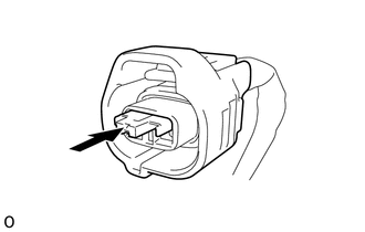
| (2) Install the retainer to the coupler. | |
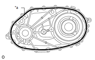
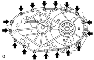
23. INSTALL REAR TRANSFER CASE
| (a) Apply seal packing to the rear transfer case as shown in the illustration.
Seal packing: Toyota Genuine Seal Packing 1281, Three Bond 1281 or equivalent Text in Illustration
NOTICE: If
the removed rear transfer case will be reused: After removing the rear
transfer case, be sure to perform the following before reinstalling it:
1) using a knife, cut off any old seal packing on the contact surface of
the rear transfer case, 2) clean off any remaining old seal packing
from the contact surface of the rear transfer case, and 3) reapply seal
packing to the rear transfer case. | |
| (b) Using a 40 IP ''TORX PLUS'' socket wrench or T40 ''TORX'' socket wrench, install the 17 bolts.
Torque: 35 N·m {357 kgf·cm, 26 ft·lbf} NOTICE: Tighten
the bolts of the rear transfer case within 10 minutes of applying the
seal packing. The seal packing will dry very quickly. | |
24. INSTALL TRANSFER INDICATOR SWITCH 
25. INSTALL TRANSFER OUTPUT SHAFT TYPE T OIL SEAL
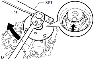
26. INSTALL OUTPUT SHAFT COMPANION FLANGE SUB-ASSEMBLY (REAR)
(a) Install the output shaft companion flange sub-assembly (rear) onto the rear transfer output shaft.
| (b) Using SST, hold the output shaft companion flange sub-assembly (rear).
SST: 09330-00021 | |
(c) Using a 30 mm socket wrench, install a new O-ring and a new transfer output shaft nut.
Torque: 127 N·m {1295 kgf·cm, 94 ft·lbf} Text in Illustration
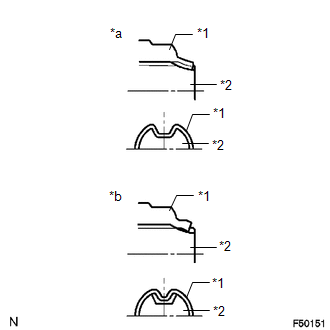
| (d) Using a chisel and hammer, stake the transfer output shaft nut. Text in Illustration |
*1 | Transfer Output Shaft Nut | |
*2 | Rear Transfer Output Shaft | |
*a | Correct | |
*b | Incorrect | |
|
27. INSTALL TRANSFER SHIFT ACTUATOR ASSEMBLY
28. INSTALL WIRING HARNESS CLAMP BRACKET
| (a) Install the wiring harness clamp bracket with the 2 bolts.
Torque: 9.5 N·m {97 kgf·cm, 84 in·lbf} | |
(b) Connect the connector and 3 clamps.
| (c) Install the 3 wiring harness clamp brackets with the 3 bolts.
Torque: 8.0 N·m {82 kgf·cm, 71 in·lbf} NOTICE: Install the wiring harness clamp bracket in the correct direction. |
|
29. INSTALL LOWER TRANSFER CASE PROTECTOR (a) Install the lower transfer case protector with the 4 bolts.
Torque: 22 N·m {219 kgf·cm, 16 ft·lbf} |