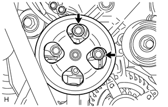
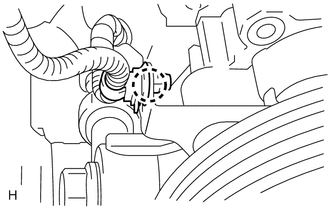
INSTALLATION PROCEDURE 1. INSTALL VANE PUMP ASSEMBLY HINT: Before performing the following procedures, move the spacer until the vane pump can be installed. 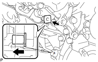 Text in Illustration Text in Illustration
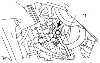
2. INSTALL PRESSURE FEED TUBE (a) Install a new gasket to the pressure feed tube.
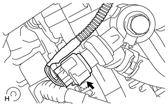
3. CONNECT POWER STEERING OIL PRESSURE SENSOR CONNECTOR
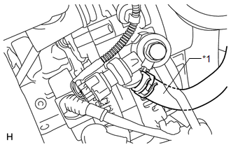
4. CONNECT NO. 1 OIL RESERVOIR TO PUMP HOSE
5. CONNECT WIRE HARNESS CLAMP
6. INSTALL FAN AND GENERATOR V BELT 7. INSTALL AIR CLEANER CASE SUB-ASSEMBLY
8. INSTALL V-BANK COVER SUB-ASSEMBLY 9. ADD POWER STEERING FLUID 10. BLEED POWER STEERING FLUID 11. INSPECT FOR POWER STEERING FLUID LEAK 12. INSTALL NO. 1 ENGINE UNDER COVER 13. CONNECT CABLE TO NEGATIVE BATTERY TERMINAL NOTICE: Some systems need to be initialized after the cable is reconnected (See page
|
Toyota Tundra Service Manual > Vehicle Stability Control System: High Power Supply Voltage Malfunction (C1417)
DESCRIPTION If a malfunction is detected in the power supply circuit, the skid control ECU (brake actuator assembly) stores this DTC and the fail-safe function prohibits ABS operation. This DTC is stored when the +BS terminal voltage deviates due to a malfunction in a power supply or charging system ...