COMPONENTS ILLUSTRATION 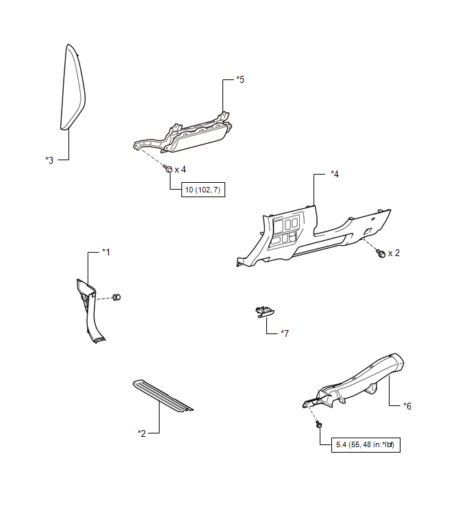
ILLUSTRATION 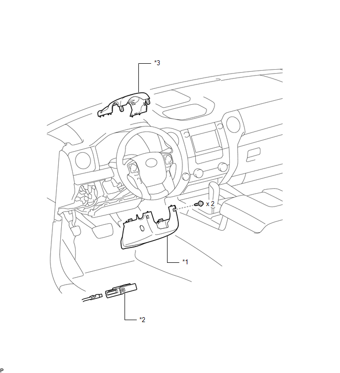
|
Toyota Tundra Service Manual > Navigation System: Operation Check
OPERATION CHECK 1. CHECK NAVIGATION SYSTEM NORMAL CONDITION (a) If the cause of a symptom is any of the following, the corresponding symptom is normal; it is not a malfunction. Symptom Answer A longer route than expected is chosen. Depending on the road conditions, the navigation receiver assembly m ...


