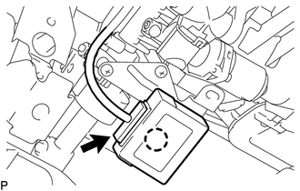
INSTALLATION PROCEDURE 1. INSTALL MULTIPLEX TILT AND TELESCOPIC ECU
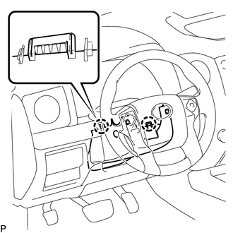
(b) Connect the ECU connector. 2. INSTALL NO. 3 AIR DUCT SUB-ASSEMBLY Click here 3. INSTALL LOWER NO. 1 INSTRUMENT PANEL AIRBAG ASSEMBLY Click here 4. INSTALL LOWER INSTRUMENT PANEL FINISH PANEL SUB-ASSEMBLY LH Click here 5. INSTALL COWL SIDE TRIM BOARD LH Click here 6. INSTALL FRONT DOOR SCUFF PLATE LH Click here 7. INSTALL INSTRUMENT SIDE PANEL LH Click here 8. INSTALL LOWER STEERING COLUMN COVER
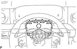
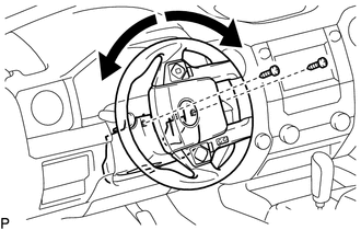
9. INSTALL UPPER STEERING COLUMN COVER
(b) Attach the 4 clips to install the upper steering cover onto the instrument panel cluster finish panel.
10. CONNECT CABLE FROM NEGATIVE BATTERY TERMINAL Torque: 5.4 N·m {55 kgf·cm, 48 in·lbf} NOTICE: When disconnecting the cable. some systems need to be initialized after the cable is reconnected (See page
11. CHECK SRS WARNING LIGHT (See page
|
Toyota Tundra Owners Manual > Opening, closing the
windows and moon roof: Moon roof
Use the overhead switches to open and close the moon roof and tilt it up and down. Opening and closing Opens the moon roof* Closes the moon roof* *: Lightly press either way of the moon roof switch to stop the moon roof partway. Tilting up and down Tilts the moon roof up* Tilts the moon roof down* ...