REMOVAL PROCEDURE 1. PRECAUTION NOTICE: After
turning the ignition switch off, waiting time may be required before
disconnecting the cable from the battery terminal. Therefore, make sure
to read the disconnecting the cable from the battery terminal notice
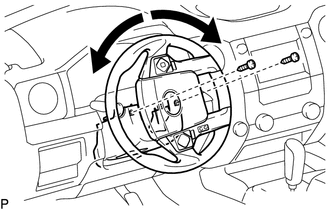
before proceeding with work (See page 2. DISCONNECT CABLE FROM NEGATIVE BATTERY TERMINAL CAUTION: Wait at least 90 seconds after disconnecting the cable from the negative (-) battery terminal to prevent airbag and seat belt pretensioner activation. 3. REMOVE UPPER STEERING COLUMN COVER
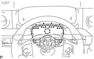
(b) Detach the 4 clips.
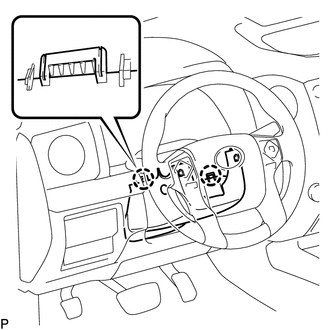
4. REMOVE LOWER STEERING COLUMN COVER
5. REMOVE INSTRUMENT SIDE PANEL LH Click here
6. REMOVE FRONT DOOR SCUFF PLATE LH Click here 7. REMOVE COWL SIDE TRIM BOARD LH Click here 8. REMOVE LOWER INSTRUMENT PANEL FINISH PANEL SUB-ASSEMBLY LH 9. REMOVE LOWER NO. 1 INSTRUMENT PANEL AIRBAG ASSEMBLY 10. REMOVE NO. 3 AIR DUCT SUB-ASSEMBLY 11. REMOVE MULTIPLEX TILT AND TELESCOPIC ECU
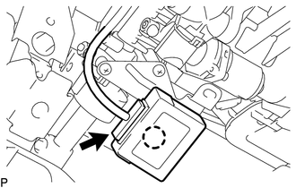
(b) Detach the claw to remove the multiplex tilt and telescopic ECU. |
Toyota Tundra Service Manual > Brake System: Problem Symptoms Table
PROBLEM SYMPTOMS TABLE HINT: Use the table below to help determine the cause of the problem symptom. The potential causes of the symptoms are listed in order of probability in the "Suspected Area" column of the table. Check each symptom by checking the suspected areas in the order they are listed. R ...

 ).
).