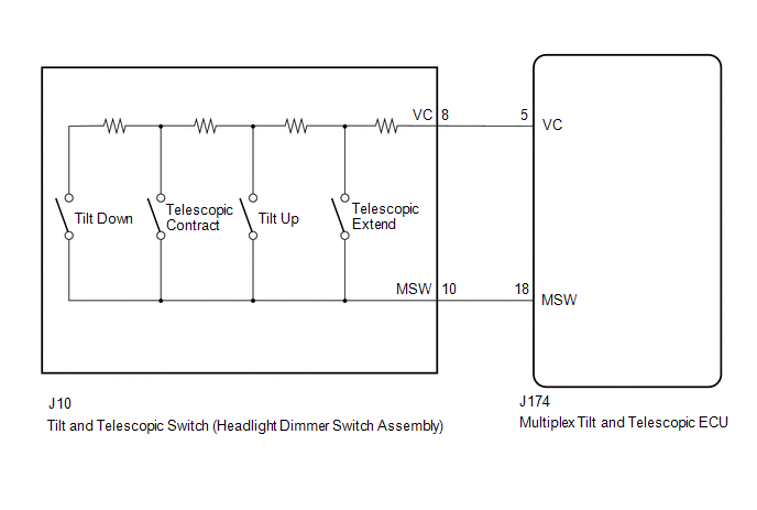
DESCRIPTION Different
voltage values are sent to the multiplex tilt and telescopic ECU by
operating the tilt and telescopic switch (headlight dimmer switch
assembly). The multiplex tilt and telescopic ECU then judges which motor
and in which direction that motor should operate based on the voltage
value. |
DTC Code | Detection Condition |
Trouble Area | | B2603 |
When
operating the tilt and telescopic switch (headlight dimmer switch
assembly), an abnormal voltage value is sent to the multiplex tilt and
telescopic ECU. |
- Tilt and telescopic switch (headlight dimmer switch assembly)
- Harness or connector
- Multiplex tilt and telescopic ECU
| WIRING DIAGRAM
 PROCEDURE
| 1. |
READ VALUE USING TECHSTREAM (TILT UP/DOWN SWITCH, TELESCOPIC SHORT/LONG SWITCH) |
(a) Turn the ignition switch off. (b) Connect the Techstream to the DLC3.
(c) Turn the ignition switch to ON. (d) Turn the Techstream on.
(e) Check the tilt and telescopic switch (headlight dimmer switch assembly).
(f) Enter the following menus: Body Electrical / Tilt & Telescopic / Data List. Body Electrical / Tilt & Telescopic / Data List |
Tester Display | Measurement Item |
Range | Normal Condition |
Diagnostic Note | |
Tilt Up Switch | Input state of tilt up switch |
ON or OFF | ON: Tilt up switch activated
OFF: Tilt up switch not activated |
- | | Tilt Down Switch |
Input state of tilt down switch |
ON or OFF | ON: Tilt down switch activated
OFF: Tilt down switch not activated |
- | | Telesco Short Switch |
Input state of telescopic contract switch |
ON or OFF | ON: Telescopic contract switch activated
OFF: Telescopic contract switch not activated |
- | | Telesco Long Switch |
Input state of telescopic extend switch |
ON or OFF | ON: Telescopic extend switch activated
OFF: Telescopic extend switch not activated |
- | OK: "ON" is displayed on the Techstream screen when each switch is turned on.
"OFF" is displayed on the Techstream screen when each switch is turned off.
| NG |
 | GO TO STEP 3 |
|
OK |
 | |
(a) Clear the DTCs.
Click here  (b) Check for DTCs.
Click here
| Result |
Proceed to | | DTCs are output. |
A | | DTCs are not output. |
B |
| A |
| REPLACE MULTIPLEX TILT AND TELESCOPIC ECU |
| B |
| USE SIMULATION METHOD TO CHECK |
| 3. |
CHECK HARNESS AND CONNECTOR (MULTIPLEX TILT AND TELESCOPIC ECU - TILT AND TELESCOPIC SWITCH (HEADLIGHT DIMMER SWITCH ASSEMBLY)) |
(a) Disconnect the J174 multiplex tilt and telescopic ECU connector. (b) Disconnect the J10 tilt and telescopic switch (headlight dimmer switch assembly) connector.
(c) Measure the resistance according to the value(s) in the table below.
Standard Resistance: |
Tester Connection | Condition |
Specified Condition | |
J174-5 (VC) - J10-8 (VC) |
Always | Below 1 Ω | |
J174-18 (MSW) - J10-10 (MSW) |
Always | Below 1 Ω | |
J174-5 (VC) or J10-8 (VC) - Body ground |
Always | 10 kΩ or higher | |
J174-18 (MSW) or J10-10 (MSW) - Body ground |
Always | 10 kΩ or higher |
| NG |
| REPAIR OR REPLACE HARNESS OR CONNECTOR |
|
OK | |
| |
| 4. |
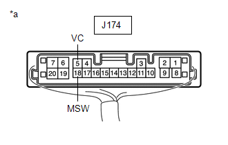
CHECK MULTIPLEX TILT AND TELESCOPIC ECU (VC TERMINAL VOLTAGE) |
| (a) Reconnect the J174 multiplex tilt and telescopic ECU connector. |
 |
|
*a | Component with harness connected
(Multiplex Tilt and Telescopic ECU) | | |
(b) Measure the voltage according to the value(s) in the table below. Standard Voltage: |
Tester Connection | Condition |
Specified Condition | |
J174-5 (VC) - J174-18 (MSW) |
Ignition switch ON | 4.9 to 5.1 V |
| NG |
| REPLACE MULTIPLEX TILT AND TELESCOPIC ECU |
|
OK | |
| |
| 5. |
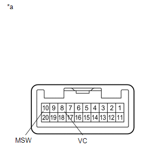
CHECK TILT AND TELESCOPIC SWITCH (HEADLIGHT DIMMER SWITCH ASSEMBLY) |
| (a) Remove the tilt and telescopic switch (headlight dimmer switch assembly).
Click here |
 |
|
*a | Component without harness connected
(Tilt and Telescopic Switch (Headlight Dimmer Switch Assembly)) | | |
(b) Measure the resistance according to the value(s) in the table below.
Standard Resistance: |
Tester Connection | Condition |
Specified Condition | |
8 (VC) - 10 (MSW) | Tilt up |
342 to 378 Ω | |
Tilt down | 1890.5 to 2089.5 Ω | |
Telescopic contract | 750.5 to 829.5 Ω | |
Telescopic extend | 152 to 168 Ω |
| OK |
| REPLACE MULTIPLEX TILT AND TELESCOPIC ECU |
| NG |
| REPLACE HEADLIGHT DIMMER SWITCH ASSEMBLY | | 

