COMPONENTS ILLUSTRATION 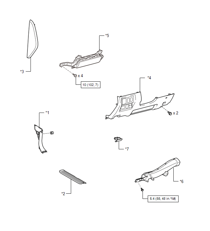
ILLUSTRATION 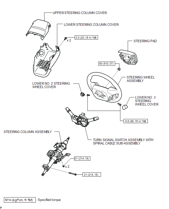 ILLUSTRATION 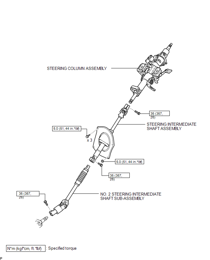 ILLUSTRATION 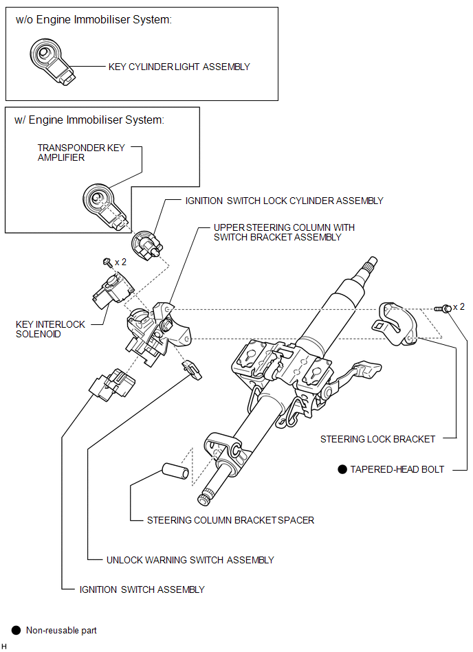 |
Toyota Tundra Service Manual > Differential System: Problem Symptoms Table
PROBLEM SYMPTOMS TABLE HINT: Use the table below to help determine the cause of problem symptoms. If multiple suspected areas are listed, the potential causes of the symptoms are listed in order of probability in the "Suspected Area" column of the table. Check each symptom by checking the suspected ...


