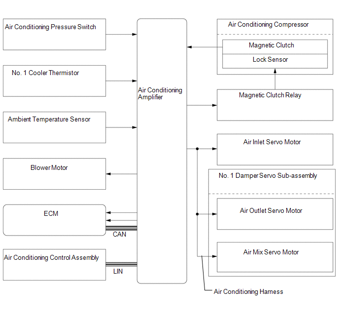
Toyota Tundra Service Manual: System Diagram

SYSTEM DIAGRAM

Communication table

Sender

Receiver

Signal

Line

Air Conditioning Control Assembly

Air Conditioning Amplifier

Air conditioning control signal

LIN

ECM

Air Conditioning Amplifier

  • Engine speed
  • Engine coolant temperature signal

CAN

    System Description

    Terminals Of Ecu

    See More:

    Toyota Tundra Service Manual > Sfi System: Bank 1 Air-Fuel Ratio Imbalance (P219A-P219F,P21A0-P21A3)
    DESCRIPTION Refer to DTC P0300 (See page ). Refer to DTC P2195 (See page ). Refer to DTC P2197 (See page ). DTC No. DTC Detection Condition Trouble Area P219A The difference in air fuel ratios between the cylinders exceeds the threshold (2 trip detection logic). Fuel injector assembly Intake system ...

    Toyota Tundra Owners Manual

    Toyota Tundra Service Manual

    © 2026 Copyright www.ttundra.com
    0.0104