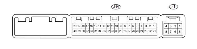
TERMINALS OF ECU
1. CHECK AIR CONDITIONING AMPLIFIER
(a) Measure the voltage and resistance according to the value(s) in the table
below.
HINT:
Check from the rear of the connector with it connected to the air conditioning
amplifier.
|
Terminal No. (Symbols)
|
Wiring Color
|
Terminal Description
|
Condition
|
Specified Condition
|
|
J19-1 (IG+) - J19-14 (GND)
|
P - W-B
|
Ignition power supply
|
Ignition switch ON
|
11 to 14 V
|
|
Ignition switch OFF
|
Below 1 V
|
|
J19-21 (B) - J19-14 (GND)
|
BR - W-B
|
Battery power source
|
Always
|
11 to 14 V
|
|
J19-14 (GND) - Body ground
|
W-B - Body ground
|
Ground
|
Always
|
Below 1 Ω
|
|
J19-5 (TAM) - J19-14 (GND)
|
V - W-B
|
Ambient temperature sensor signal
|
Ignition switch ON at 25°C (77°F)
|
1.35 to 1.75 V
|
|
Ignition switch ON at 40°C (104°F)
|
0.9 to 1.2 V
|
|
J19-8 (LOCK) - J19-14 (GND)
|
SB - W-B
|
Compressor lock sensor signal
|
Engine is running
Blower switch LO
A/C switch ON
|
Pulse generation
(see waveform 1)
|
|
J19-23 (BLW) - J19-14 (GND)
|
LG - W-B
|
Blower motor control signal
|
Ignition switch ON
Blower switch LO
|
Pulse generation
(see waveform 2)
|
|
J19-20 (MGC) - J19-14 (GND)
|
P - W-B
|
Compressor magnetic clutch operation signal
|
Engine is running
Blower switch LO
A/C switch OFF
|
11 to 14 V
|
|
Engine is running
Blower switch LO
A/C switch ON
|
Below 1 V
|
|
J19-13 (SG-2) - Body ground
|
G - Body ground
|
Ground for ambient temperature sensor
|
Always
|
Below 1 Ω
|
|
J19-37 (LIN1) - J19-14 (GND)
|
SB - W-B
|
LIN communication signal
|
Ignition switch ON
|
Pulse generation
|
|
J19-11 (CANH) - J19-14 (GND)
|
B - W-B
|
Hi-level CAN bus line
|
Ignition switch ON
|
Pulse generation
(see waveform 3)
|
|
J19-12 (CANL) - J19-14 (GND)
|
W - W-B
|
Lo-level CAN bus line
|
Ignition switch ON
|
Pulse generation
(see waveform 4)
|
|
z1-2 (BUS G) - Body ground
|
-
|
Ground for BUS IC
|
Always
|
Below 2 V
|
|
z1-3 (BUS) - z1-2 (BUS G)
|
-
|
BUS IC control signal
|
Ignition switch OFF → ON
|
Pulse generation
|
|
z1-4 (B BUS) - z1-2 (BUS G)
|
-
|
Power supply for BUS IC
|
Always
|
11 to 14 V
|
|
z1-5 (SGA) - Body ground
|
-
|
Ground for No. 1 cooler thermistor
|
Always
|
Below 2 V
|
|
z1-6 (TEA) - z1-5 (SGA)
|
-
|
No. 1 cooler thermistor signal
|
Ignition switch ON
No. 1 cooler thermistor at 0°C (32°F)
|
1.7 to 2.1 V
|
|
Ignition switch ON
No. 1 cooler thermistor at 15°C (59°F)
|
0.7 to 1.3 V
|
(b) Using an oscilloscope, check waveform 1.
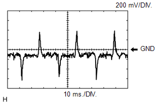 Compressor lock signal Compressor lock signal
|
Terminal No. (Symbols)
|
Tool Setting
|
Condition
|
|
J19-8 (LOCK) - J19-14 (GND)
|
200 mV/DIV., 10 ms./DIV.
|
Engine is running
Blower switch LO
A/C switch ON
|
(c) Using an oscilloscope, check waveform 2.
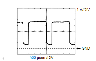 Blower motor control signal Blower motor control signal
|
Terminal No. (Symbols)
|
Tool Setting
|
Condition
|
|
J19-23 (BLW) - J19-14 (GND)
|
1 V/DIV., 500 μsec./DIV.
|
Ignition switch ON
Blower switch LO
|
HINT:
When the blower level is increased, the duty ratio changes accordingly.
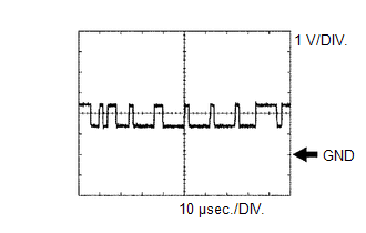
(d) Using an oscilloscope, check waveform 3.
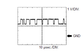 CAN communication signal CAN communication signal
|
Terminal No. (Symbols)
|
Tool Setting
|
Condition
|
|
J19-11 (CANH) - J19-14 (GND)
|
1 V/DIV., 10 μsec./DIV.
|
Ignition switch ON
|
HINT:
The waveform varies depending on the CAN communication signal.
(e) Using an oscilloscope, check waveform 4.
 CAN communication signal CAN communication signal
|
Terminal No. (Symbols)
|
Tool Setting
|
Condition
|
|
J19-12 (CANL) - J19-14 (GND)
|
1 V/DIV., 10 μsec./DIV.
|
Ignition switch ON
|
HINT:
The waveform varies depending on the CAN communication signal.
2. CHECK AIR CONDITIONING CONTROL ASSEMBLY

(a) Disconnect the J127 air conditioning control assembly connector.
(b) Measure the voltage and resistance according to the value(s) in the table
below.
|
Terminal No. (Symbols)
|
Wiring Color
|
Terminal Description
|
Condition
|
Specified Condition
|
|
J127-4 (IG+) - J127-5 (GND)
|
SB - W-B
|
Ignition power supply
|
Ignition switch ON
|
11 to 14 V
|
|
Ignition switch OFF
|
Below 1 V
|
|
J127-5 (GND) - Body ground
|
W-B - Body ground
|
Ground
|
Always
|
Below 1 Ω
|
|
J127-7 (STX) - J127-5 (GND)
|
SB - W-B
|
LIN communication signal
|
Ignition switch ON
|
Pulse generation
|
| 

