COMPONENTS ILLUSTRATION 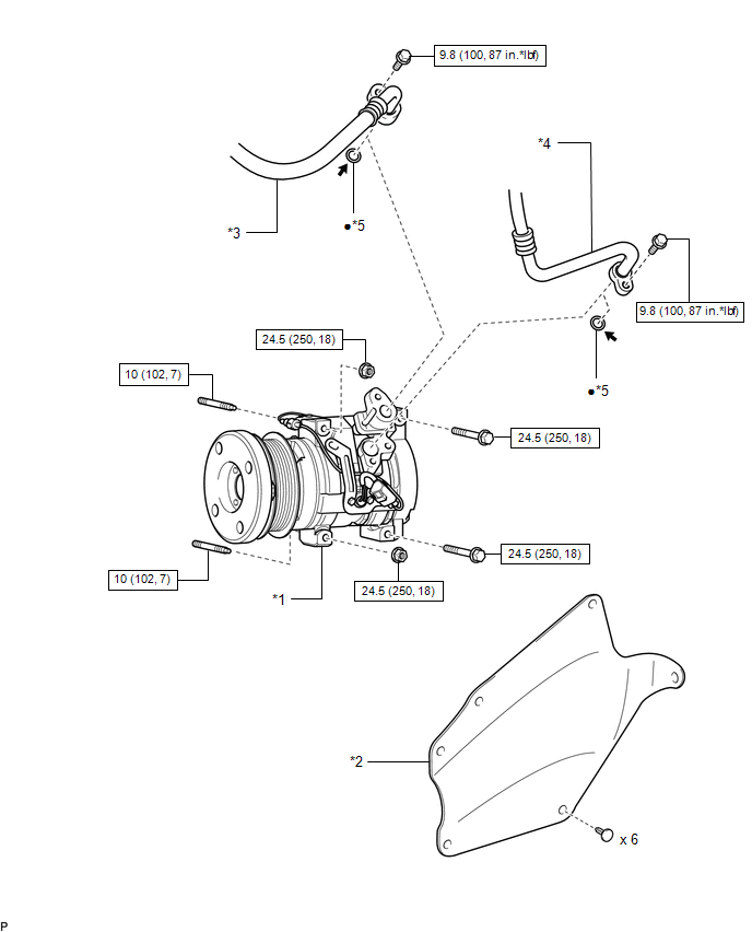
ILLUSTRATION 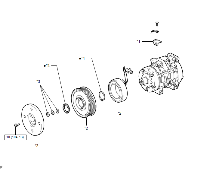
|
Toyota Tundra Owners Manual > For safe use: For safe driving
For safe driving, adjust the seat and mirror to an appropriate position before driving. Correct driving posture Adjust the angle of the seatback so that you are sitting straight up and so that you do not have to lean forward to steer. Adjust the seat so that you can depress the pedals fully and so ...


