INSTALLATION PROCEDURE 1. INSTALL NO. 1 COOLER THERMISTOR NOTICE: If reusing the evaporator, do not insert the No. 1 cooler thermistor into a location where the No. 1 cooler thermistor was previously inserted. Insert the No. 1 cooler thermistor within range C shown in the illustration. 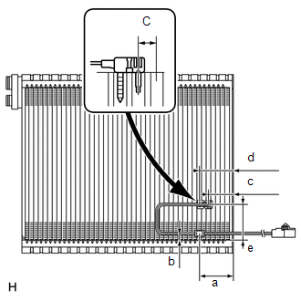
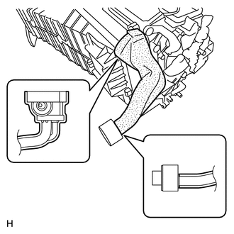
(a) Install the No. 1 cooler thermistor to the No. 1 cooler evaporator sub-assembly as shown in the illustration.
2. INSTALL NO. 1 COOLER EVAPORATOR SUB-ASSEMBLY (a) Install the No. 1 cooler evaporator sub-assembly to the blower assembly. 3. INSTALL BLOWER ASSEMBLY (a) Attach the 3 claws to install the blower assembly. (b) Install the 6 screws.
(d) Attach the 3 claws to install the heater clamp. 4. INSTALL AIR CONDITIONING AMPLIFIER ASSEMBLY
5. INSTALL NO. 3 AIR DUCT SUB-ASSEMBLY
6. INSTALL AIR CONDITIONING UNIT (See page |
Toyota Tundra Service Manual > Airbag System: Vehicle Control History
VEHICLE CONTROL HISTORY Function Overview (a) The vehicle control history is a function that records control data (record data) when triggered by specific vehicle behavior. When DTCs are not detected according to information provided by customers, by checking the vehicle control history, it is possi ...