INSPECTION PROCEDURE 1. INSPECT FRONT DOOR LOCK ASSEMBLY LH (a) Check the door lock motor. (1) Apply battery voltage to the door lock motor and check operation of the door lock motor. 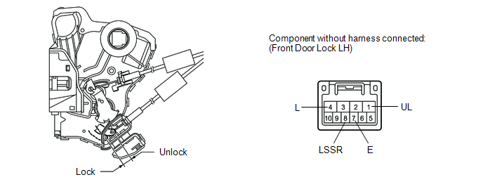
OK:
(b) Check the door lock position switch. (1) Measure the resistance according to the value(s) in the table below. Standard resistance:
(c) Check the door lock and unlock switch. (1) Measure the resistance according to the value(s) in the table below. 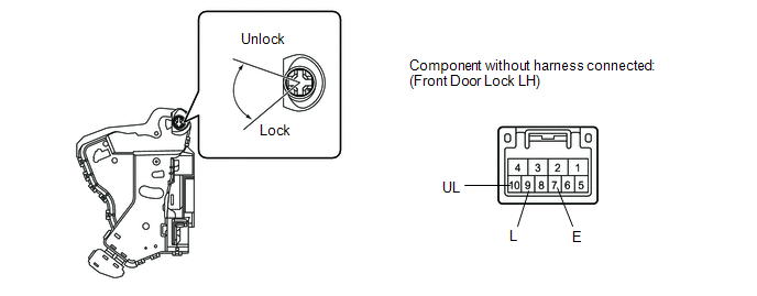
Standard resistance:
2. INSPECT FRONT DOOR LOCK ASSEMBLY RH (a) Check the door lock motor. (1) Apply battery voltage to the door lock motor and check operation of the door lock motor. 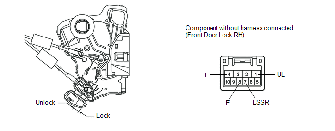
OK:
(b) Check the door lock position switch. (1) Measure the resistance according to the value(s) in the table below. Standard resistance:
(c) Check the door lock and unlock switch. (1) Measure the resistance according to the value(s) in the table below. 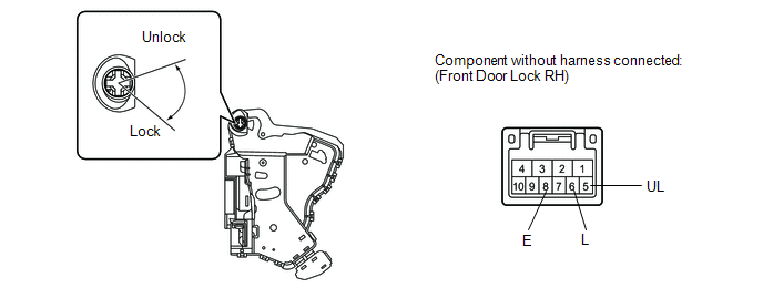
Standard resistance:
|
Toyota Tundra Service Manual > Key Reminder Warning System: How To Proceed With Troubleshooting
CAUTION / NOTICE / HINT HINT: Use the following procedures to troubleshoot the key reminder warning system. *: Use the Techstream. PROCEDURE 1. VEHICLE BROUGHT TO WORKSHOP NEXT 2. INSPECT BATTERY VOLTAGE Standard Voltage: 11 to 14 V If the voltage is below 11 V, recharge or replace the battery befor ...


