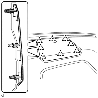
REASSEMBLY CAUTION / NOTICE / HINT HINT: A bolt without a torque specification is shown in the standard bolt chart. Click here PROCEDURE 1. INSTALL FRONT PASSENGER AIRBAG ASSEMBLY Click here 2. INSTALL NAVIGATION ANTENNA ASSEMBLY (w/ Navigation System) Click here 3. INSTALL INSTRUMENT CLUSTER FINISH PANEL REINFORCEMENT (a) Install the 2 instrument cluster finish panel reinforcements with the 2 screws <F>. 4. INSTALL NO. 1 SIDE DEFROSTER NOZZLE DUCT (a) Install the No. 1 side defroster nozzle duct with the 2 screws <E>. 5. INSTALL NO. 2 SIDE DEFROSTER NOZZLE DUCT (a) Install the No. 2 side defroster nozzle duct with the 2 screws <E>. 6. INSTALL NO. 2 HEATER TO REGISTER DUCT (a) Install the No. 2 heater to register duct with the 8 screws <E>. 7. INSTALL DEFROSTER NOZZLE ASSEMBLY 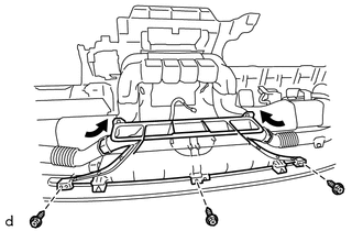
(a) Install the defroster nozzle assembly with the 3 screws <E>. (b) Connect the No. 1 side defroster nozzle duct and No. 2 side defroster nozzle duct to the defroster nozzle assembly. 8. INSTALL NO. 1 INSTRUMENT PANEL PIN HINT: Use the same procedure to install the No. 1 instrument panel pin on the other side. (a) Install the No. 1 instrument panel pin with the screw <E>. 9. INSTALL FRONT NO. 4 SPEAKER ASSEMBLY Click here 10. INSTALL NO. 1 SPEAKER HOLE COVER (a) Connect the connector.
11. INSTALL BOX BOTTOM MAT (a) Install the box bottom mat. |
Toyota Tundra Service Manual > Rear Leaf Spring: Disassembly
DISASSEMBLY PROCEDURE 1. REMOVE REAR SPRING LEAF BUSH (a) Put matchmarks on the bush on the front side of the vehicle. (1) Align the leaf spring with the openings and put matchmarks. (b) Use SST and a press, press out the bushes on both sides of the vehicle. SST: 09950-60010 09951-00350 SST: 09950-7 ...