INSTALLATION CAUTION / NOTICE / HINT HINT: A bolt without a torque specification is shown in the standard bolt chart (See
page PROCEDURE 1. INSTALL NO. 1 INSTRUMENT PANEL CLIP
2. INSTALL NO. 3 INSTRUMENT PANEL STAY
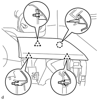
3. INSTALL INSTRUMENT PANEL SUB-ASSEMBLY (a) Set the instrument panel sub-assembly and attach the 5 claws. (b) Install the 2 nuts <C> and 3 bolts <B>. (c) Install the 2 bolts <G>. Torque: 20 N·m {204 kgf·cm, 15 ft·lbf} 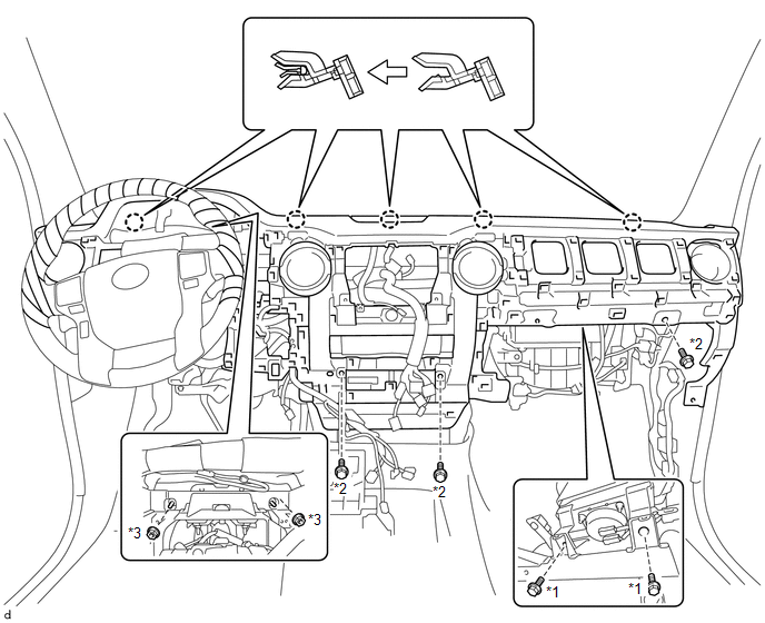 Text in Illustration Text in Illustration
(d) for Automatic Air Conditioning System: Attach the 2 claws to connect the cooler thermistor. (e) Connect each connector and attach each wire harness clamp. 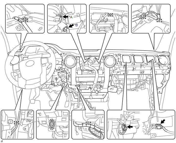 Text in Illustration Text in Illustration
4. INSTALL FRONT NO. 2 SPEAKER ASSEMBLY LH
5. INSTALL INSTRUMENT PANEL SPEAKER PANEL SUB-ASSEMBLY
6. INSTALL FRONT NO. 2 SPEAKER ASSEMBLY RH
7. INSTALL NO. 2 INSTRUMENT PANEL SPEAKER PANEL SUB-ASSEMBLY
8. INSTALL FRONT PILLAR GARNISH LH
9. INSTALL FRONT DOOR OPENING TRIM WEATHERSTRIP LH
10. INSTALL FRONT PILLAR GARNISH RH
11. INSTALL FRONT DOOR OPENING TRIM WEATHERSTRIP RH HINT: Use the same procedure described for the LH side. 12. INSTALL CENTER INSTRUMENT CLUSTER FINISH PANEL SUB-ASSEMBLY
13. INSTALL RADIO AND DISPLAY RECEIVER ASSEMBLY WITH BRACKET
14. INSTALL LOWER CENTER INSTRUMENT PANEL FINISH PANEL WITH AIR CONDITIONING CONTROL ASSEMBLY
15. INSTALL NO. 2 INSTRUMENT CLUSTER FINISH PANEL GARNISH
16. INSTALL LOWER INSTRUMENT PANEL FINISH PANEL SUB-ASSEMBLY RH
17. INSTALL INSTRUMENT SIDE PANEL RH
18. INSTALL NO. 4 INSTRUMENT REGISTER SUB-ASSEMBLY
19. INSTALL LOWER NO. 2 INSTRUMENT PANEL AIRBAG ASSEMBLY
20. INSTALL LOWER INSTRUMENT PANEL
21. INSTALL NO. 2 INSTRUMENT PANEL UNDER COVER SUB-ASSEMBLY
22. INSTALL COMBINATION METER ASSEMBLY
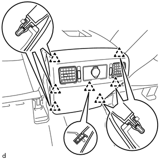
23. INSTALL INSTRUMENT CLUSTER FINISH PANEL ASSEMBLY (a) Attach the 6 clips to install the instrument cluster finish panel assembly. (b) Install the 2 clips. 24. INSTALL INSTRUMENT CLUSTER FINISH PANEL ORNAMENT
25. INSTALL NO. 2 SWITCH HOLE BASE (a) Connect each connector.
26. INSTALL NO. 1 INSTRUMENT CLUSTER FINISH PANEL GARNISH
27. INSTALL LOWER NO. 1 INSTRUMENT PANEL AIRBAG ASSEMBLY
28. INSTALL LOWER INSTRUMENT PANEL FINISH PANEL SUB-ASSEMBLY LH
29. INSTALL COWL SIDE TRIM BOARD LH
30. INSTALL FRONT DOOR SCUFF PLATE LH
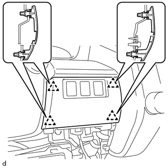
31. INSTALL COWL SIDE TRIM BOARD RH HINT: Use the same procedure described for the LH side. 32. INSTALL FRONT DOOR SCUFF PLATE RH HINT: Use the same procedure described for the LH side. 33. INSTALL FRONT CONSOLE BOX (a) Install the front console box with the 5 screws <E>. (b) Install the 2 clips and attach the connector. 34. INSTALL REAR CONSOLE BOX ASSEMBLY (a) Install the rear console box assembly with the 2 screws <E> and 4 bolts <B>. (b) Connect the 2 connectors. 35. INSTALL CONSOLE BOX CARPET (a) Install the console box carpet. 36. INSTALL REAR CONSOLE END PANEL SUB-ASSEMBLY (a) w/ Power Outlet Socket: Attach the 2 wire harness clamps and connect the connector.
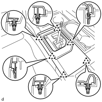
37. INSTALL UPPER CONSOLE PANEL SUB-ASSEMBLY (a) Attach the 12 clips to install the upper console panel sub-assembly. 38. INSTALL UPPER REAR CONSOLE PANEL SUB-ASSEMBLY
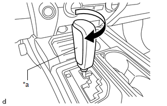
39. INSTALL SHIFT LEVER KNOB SUB-ASSEMBLY
40. INSTALL INSTRUMENT SIDE PANEL LH
41. INSTALL NO. 1 INSTRUMENT PANEL REGISTER SUB-ASSEMBLY
42. CONNECT CABLE TO NEGATIVE BATTERY TERMINAL NOTICE: When disconnecting the cable, some systems need to be initialized after the cable
is reconnected (See page 43. RESTORE AUTOAWAY/RETURN FUNCTION (for Power Tilt and Power Telescopic Steering Column) (a) Restore the Autoaway/Return function setting to the previous condition by
changing the customize parameter (See page 44. CHECK SRS WARNING LIGHT (See page |
Toyota Tundra Service Manual > Rear Door(for Double Cab): On-vehicle Inspection
ON-VEHICLE INSPECTION PROCEDURE 1. INSPECT REAR DOOR PANEL SUB-ASSEMBLY LH (a) Check that the clearance measurements of areas A to J are within the standard range. Standard measurement: Area Specified Condition Area Specified Condition A 4.7 to 7.7 mm (0.185 to 0.303 in.) F 2.5 to 5.5 mm (0.0984 to ...

 ).
).