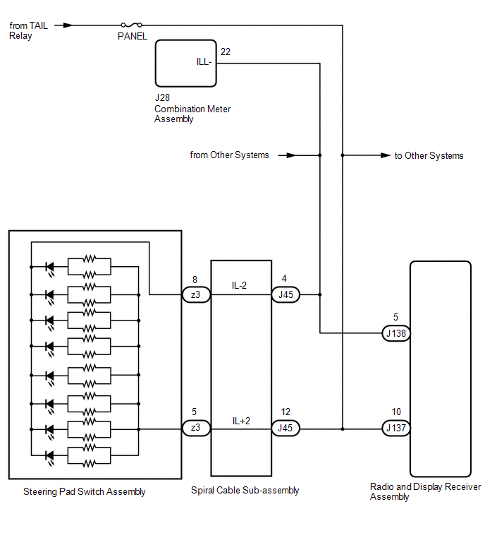
DESCRIPTION Power is
supplied to the radio and display receiver assembly and steering pad
switch assembly illumination when the light control switch is in the
tail or head position. WIRING DIAGRAM
 CAUTION / NOTICE / HINT
NOTICE:
- The vehicle is equipped with a Supplemental Restraint System (SRS) which
includes components such as airbags. Before servicing (including
removal or installation of parts), be sure to read the precaution for
Supplemental Restraint System.
Click here 
- Inspect the fuses for circuits related to this system before performing the following procedure.
- After turning the ignition switch off, waiting time may be required
before disconnecting the cable from the negative (-) battery terminal.
Therefore, make sure to read the disconnecting the cable from the
negative (-) battery terminal notices before proceeding with work.
PROCEDURE |
1. | CHECK METER / GAUGE SYSTEM |
(a) Check if the rheostat function operates normally. OK: The rheostat function operates normally.
| NG |
 | GO TO METER / GAUGE SYSTEM |
|
OK |
 | |
(a) Check if the instrument panel illumination comes on normally.
OK: The instrument panel illumination comes on normally.
| NG |
| GO TO LIGHTING SYSTEM |
|
OK | |
| |
(a)
Check if the illumination for the steering pad switch assembly or radio
and display receiver assembly comes on when the light control switch is
turned to the head or tail position. |
Result | Proceed to | |
Illumination for steering pad switch assembly does not come on. |
A | | Illumination for navigation receiver assembly does not come on. |
B |
| B |
| GO TO STEP 7 |
|
A | |
| |
| 4. |
CHECK HARNESS AND CONNECTOR (ILLUMINATION SIGNAL) |
| (a) Disconnect the spiral cable sub-assembly connector. Click here
|
 |
|
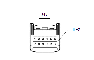
*a | Front view of wire harness connector
(to Spiral Cable Sub-assembly) | | |
(b) Measure the voltage according to the value(s) in the table below. Standard Voltage: |
Tester Connection | Switch Condition |
Specified Condition | |
J45-12 (IL+2) - Body ground |
Light control switch in the tail or head position |
11 to 14 V |
| NG |
| REPAIR OR REPLACE HARNESS OR CONNECTOR |
|
OK | |
| |
| 5. |
INSPECT STEERING PAD SWITCH ASSEMBLY | (a) Remove the steering pad switch assembly.
Click here (b) Inspect the steering pad switch assembly.
Click here
| NG |
| REPLACE STEERING PAD SWITCH ASSEMBLY |
|
OK | |
| |
| 6. |
INSPECT SPIRAL CABLE SUB-ASSEMBLY | (a) Remove the spiral cable sub-assembly.
Click here (b) Inspect the spiral cable sub-assembly.
Click here
| OK |
| REPAIR OR REPLACE HARNESS OR CONNECTOR |
| NG |
| REPLACE SPIRAL CABLE SUB-ASSEMBLY |
| 7. |
CHECK HARNESS AND CONNECTOR (ILLUMINATION SIGNAL) |
| (a) Disconnect the radio and display receiver assembly connector. |
 |
|
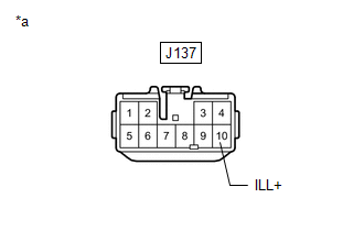
*a | Front view of wire harness connector
(to Radio and Display Receiver Assembly) | | |
(b) Measure the voltage according to the value(s) in the table below. Standard Voltage: |
Tester Connection | Switch Condition |
Specified Condition | |
J137-10 (ILL+) - Body ground |
Light control switch in tail or head position |
11 to 14 V |
| NG |
| REPAIR OR REPLACE HARNESS OR CONNECTOR |
|
OK | |
| |
| 8. |
CHECK HARNESS AND CONNECTOR (RADIO AND DISPLAY RECEIVER ASSEMBLY - COMBINATION METER ASSEMBLY) |
(a) Disconnect the J138 radio and display receiver assembly connector.
(b) Disconnect the J28 combination meter assembly connector. (c) Measure the resistance according to the value(s) in the table below.
Standard Resistance: |
Tester Connection | Condition |
Specified Condition | |
J138-5 (ILL-) - J28-22 (ILL-) |
Always | Below 1 Ω |
| OK |
| REPLACE RADIO AND DISPLAY RECEIVER ASSEMBLY |
| NG |
| REPAIR OR REPLACE HARNESS OR CONNECTOR | | 

