DESCRIPTION This circuit is from the parking brake switch assembly to the radio and display receiver assembly. WIRING DIAGRAM 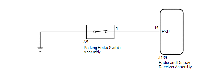 PROCEDURE
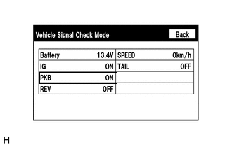
(b) Check that the display changes between ON and OFF according to the parking brake operation. OK:
HINT: This display is updated once per second. As a result, it is normal for the display to lag behind the actual parking brake operation.
(a) Disconnect the J139 radio and display receiver assembly connector. (b) Disconnect the A5 parking brake switch assembly connector. (c) Measure the resistance according to the value(s) in the table below. Standard Resistance:
(a) Remove the parking brake switch assembly (See page
(b) Inspect the parking brake switch assembly (See page
|
Toyota Tundra Service Manual > Occupant Classification System: System Description
SYSTEM DESCRIPTION 1. GENERATION DESCRIPTION (a) The occupant classification system determines whether the front passenger seat is occupied by an adult or child (with child seat) or is unoccupied, based on the load that is applied to the front passenger seat and whether the seat belt is buckled. The ...

 )]
)]