Toyota Tundra Service Manual: Interior Light Auto Cut Circuit

DESCRIPTION

When the battery saving control operates, the main body ECU (multiplex network body ECU) controls the operation of the DOME CUT relay that is built into the driver side junction block assembly to turn off the interior lights.

WIRING DIAGRAM

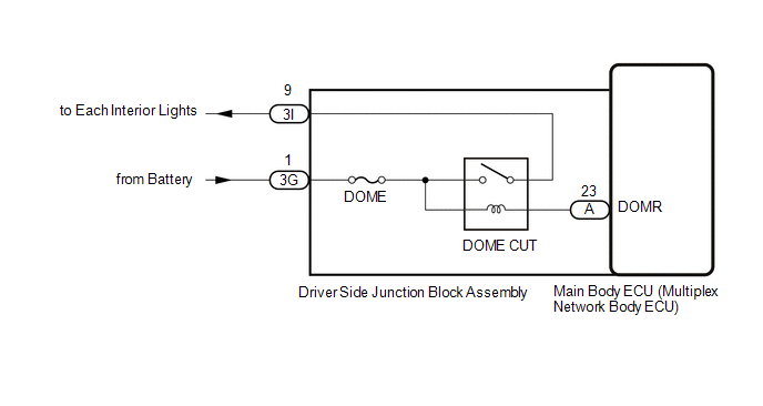
CAUTION / NOTICE / HINT

NOTICE:

Inspect the fuses for circuits related to this system before performing the following procedure.

PROCEDURE

1.

PERFORM ACTIVE TEST USING TECHSTREAM

(a) Perform the Active Test according to the display on the Techstream.

Click here

Main Body

Tester Display

Test Part

Control Range

Diagnostic Note

Relay for Interior Light Auto Cut Function

DOME relay

OFF or ON

ON: DOME CUT relay off (interior lights turn off)

OFF: DOME CUT relay on (interior lights turn on)

OK:

All of the interior lights turn off when ON is selected.

OK

PROCEED TO NEXT SUSPECTED AREA SHOWN IN PROBLEM SYMPTOMS TABLE

NG

2.

CHECK HARNESS AND CONNECTOR (DRIVER SIDE JUNCTION BLOCK ASSEMBLY - BATTERY)

(a) Disconnect the driver side junction block assembly connector.

*a

Front view of wire harness connector

(to Driver Side Junction Block Assembly)

(b) Measure the voltage according to the value(s) in the table below.

Standard Voltage:

Tester Connection

Condition

Specified Condition

3G-1 - Body ground

Always

Below 1 Ω

NG

REPAIR OR REPLACE HARNESS OR CONNECTOR

OK

3.

CHECK DRIVER SIDE JUNCTION BLOCK ASSEMBLY

(a) Remove the driver side junction block assembly.

Click here

*a

Component without harness connected

(Driver Side Junction Block Assembly)

-

-

(b) Remove the main body ECU (multiplex network body ECU) from the driver side junction block assembly.

Click here

(c) Measure the voltage according to the value(s) in the table below.

Standard Voltage:

Tester Connection

Condition

Specified Condition

3I-19 - Battery negative (-) terminal

Battery positive (+) → 3G-1

Battery negative (-) → A-23 (DOMR)

11 to 14 V

Battery not connected to 3G-1 and A-23 (DOMR)

Below 1 V

OK

REPLACE MAIN BODY ECU (MULTIPLEX NETWORK BODY ECU)

NG

REPLACE DRIVER SIDE JUNCTION BLOCK ASSEMBLY

    IG Signal Circuit

    Interior Light Circuit

    See More:

    Toyota Tundra Service Manual > Air Conditioning System(for Automatic Air Conditioning System): Diagnostic Trouble Code Chart
    DIAGNOSTIC TROUBLE CODE CHART HINT: If a trouble code is displayed during the DTC check, inspect the trouble areas listed for that code. For details of the code, refer to the "See page" below. Air conditioning system DTC Code Detection Item See page B1411/11 Room Temperature Sensor Circuit ...

    Toyota Tundra Owners Manual

    Toyota Tundra Service Manual

    © 2024 Copyright www.ttundra.com
    0.032