Toyota Tundra Service Manual: Radio Antenna Pole

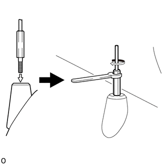
Components

COMPONENTS

ILLUSTRATION

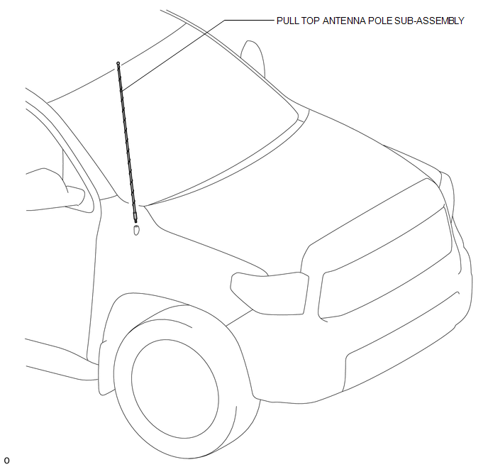
Installation

INSTALLATION

PROCEDURE

1. INSTALL PULL TOP ANTENNA POLE SUB-ASSEMBLY

(a) Install the pull top antenna pole sub-assembly and tighten it by hand until it is fully seated.

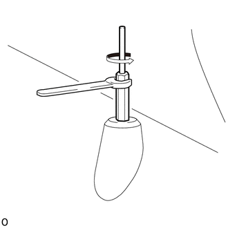
(b) Using an 8 mm (0.315 in.) wrench or antenna mast tool, tighten the pull top antenna pole sub-assembly clockwise approximately 1/8 turn (20 to 45 degrees).

HINT:

  • Do not overtighten the pull top antenna pole sub-assembly. Tighten the pull top antenna pole sub-assembly with your fingers, not your whole hand.
  • Do not use pliers to tighten the pull top antenna pole sub-assembly as it can leave marks on the pull top antenna pole sub-assembly surface.
  • The pull top antenna pole sub-assembly cannot be tightened by hand to the proper torque specification.

Torque:

3.3 N·m {3.4 kgf·cm, 29 in·lbf}

Removal

REMOVAL

PROCEDURE

1. REMOVE PULL TOP ANTENNA POLE SUB-ASSEMBLY

(a) Using an 8 mm (0.315 in.) wrench or antenna mast tool, remove the pull top antenna pole sub-assembly by turning it counterclockwise.

    Microphone Amplifier

    Radio Antenna

    See More:

    Toyota Tundra Service Manual > Dynamic Radar Cruise Control System: Radar Cruise Control Presence Determination Malfunction (Engine / HV) (C1A52)
    DESCRIPTION DTC C1A52 is stored when the ECM cannot recognize the millimeter wave radar sensor assembly. DTC No. Detection Item DTC Detection Condition Trouble Area C1A52 Radar Cruise Control Presence Determination Malfunction (Engine / HV) Approximately 17 seconds after the ignition switch is turne ...

    Toyota Tundra Owners Manual

    Toyota Tundra Service Manual

    © 2025 Copyright www.ttundra.com
    0.01