Components COMPONENTS ILLUSTRATION 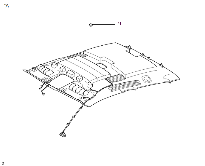
ILLUSTRATION 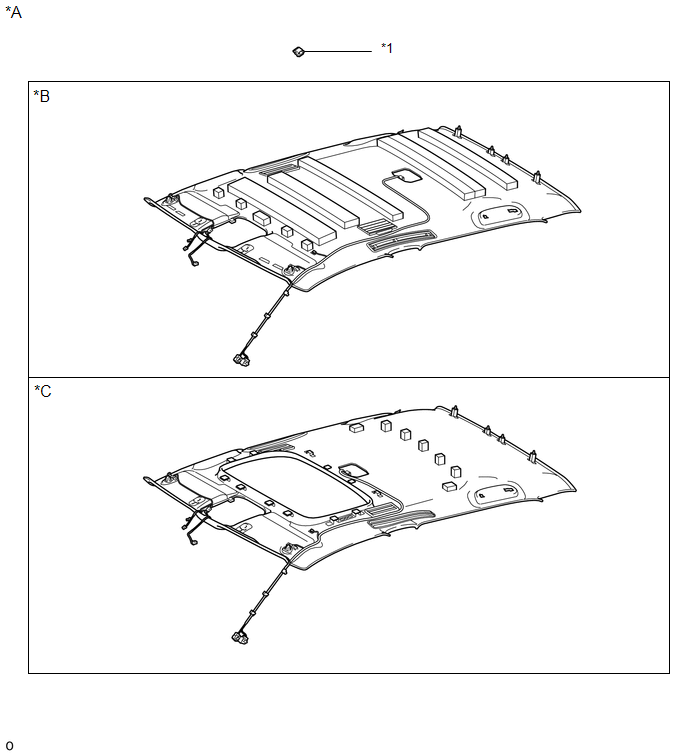
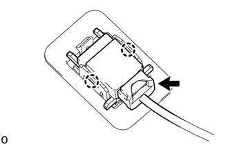
Installation INSTALLATION PROCEDURE 1. INSTALL TELEPHONE MICROPHONE ASSEMBLY
(b) Connect the connector. 2. INSTALL ROOF HEADLINING ASSEMBLY (a) for Double Cab: Click here (b) for CrewMax: Click here
Removal REMOVAL PROCEDURE 1. REMOVE ROOF HEADLINING ASSEMBLY (a) for Double Cab: Click here
(b) for CrewMax: Click here
2. REMOVE TELEPHONE MICROPHONE ASSEMBLY
(b) Detach the 2 claws and remove the telephone microphone assembly. |
Toyota Tundra Service Manual > Meter / Gauge System: Lost Communication with Brake System Control Module (U0129)
DESCRIPTION The combination meter communicates with the skid control ECU via the CAN line. DTC Code DTC Detection Condition Trouble Area U0129 When either of following conditions is detected: 15 seconds have elapsed since engine started and IG voltage 10.5 V or more No communication with skid contro ...