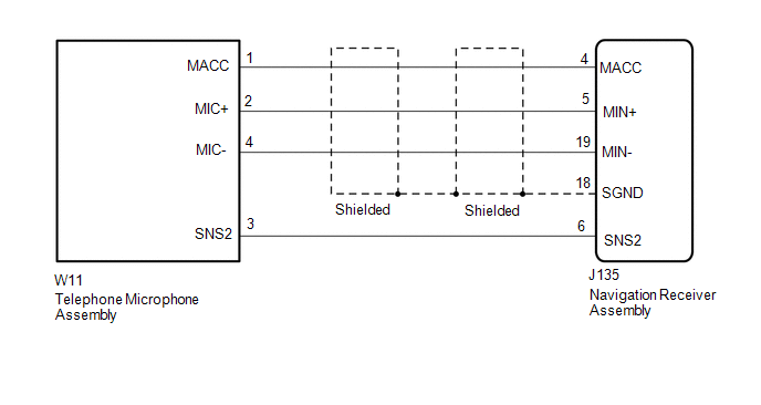
DESCRIPTION This circuit sends a microphone signal from the telephone microphone assembly to the navigation receiver assembly.
It also supplies power from the navigation receiver assembly to the telephone microphone assembly. WIRING DIAGRAM
 PROCEDURE
| 1. |
CHECK HARNESS AND CONNECTOR (NAVIGATION RECEIVER ASSEMBLY - TELEPHONE MICROPHONE ASSEMBLY) |
(a) Disconnect the J135 navigation receiver assembly connector. (b) Disconnect the W11 telephone microphone assembly connector.
(c) Measure the resistance according to the value(s) in the table below.
Standard Resistance: |
Tester Connection | Condition |
Specified Condition | |
J135-4 (MACC) - W11-1 (MACC) |
Always | Below 1 Ω | |
J135-5 (MIN+) - W11-2 (MIC+) |
Always | Below 1 Ω | |
J135-19 (MIN-) - W11-4 (MIC-) |
Always | Below 1 Ω | |
J135-6 (SNS2) - W11-3 (SNS2) |
Always | Below 1 Ω | |
J135-4 (MACC) - Body ground |
Always | 10 kΩ or higher | |
J135-5 (MIN+) - Body ground |
Always | 10 kΩ or higher | |
J135-19 (MIN-) - Body ground |
Always | 10 kΩ or higher | |
J135-18 (SGND) - Body ground |
Always | 10 kΩ or higher | |
J135-6 (SNS2) - Body ground |
Always | 10 kΩ or higher |
| NG |
 | REPAIR OR REPLACE HARNESS OR CONNECTOR |
|
OK |
 | |
| 2. |
CHECK NAVIGATION RECEIVER ASSEMBLY |
| (a) Measure the resistance according to the value(s) in the table below.
Standard Resistance: |
Tester Connection | Condition |
Specified Condition | |
J135-19 (MIN-) - Body ground |
Always | Below 1 Ω | |
J135-18 (SGND) - Body ground |
Always | Below 1 Ω | |
 |
|
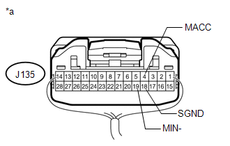
*a | Component with harness connected
(Navigation Receiver Assembly) | | |
(b) Measure the voltage according to the value(s) in the table below. Standard Voltage: |
Tester Connection | Switch Condition |
Specified Condition | |
J135-4 (MACC) - Body ground |
Ignition switch ACC | 4.75 to 5.25 V | Result |
Result | Proceed to | |
OK | A | |
NG (for Column Shift Type) |
B | | NG (for Floor Shift Type) |
C |
| B |
| REPLACE NAVIGATION RECEIVER ASSEMBLY |
| C |
| REPLACE NAVIGATION RECEIVER ASSEMBLY |
|
A | |
| |
| 3. |
CHECK TELEPHONE MICROPHONE ASSEMBLY | (a) Replace the telephone microphone assembly with a known good one (See page
 ). ). (b) Check if the same problem occurs again.
OK: Malfunction disappears. Result |
Result | Proceed to | |
OK | A | |
NG (for Column Shift Type) |
B | | NG (for Floor Shift Type) |
C |
| A |
| END (TELEPHONE MICROPHONE ASSEMBLY IS DEFECTIVE) |
| B |
| REPLACE NAVIGATION RECEIVER ASSEMBLY |
| C |
| REPLACE NAVIGATION RECEIVER ASSEMBLY | | 

