DESCRIPTION Refer to DTC P0412 (See page
 ). ). |
DTC No. | DTC Detection Condition |
Trouble Area | | P1613
P1614 | Either of following conditions (1) or (2) met:
(1) All of following conditions met (1 trip detection logic):
- Either air pump or air switching valve not operating
- Diagnostic signal from Air Injection Control Driver (AID) 80%
- Battery voltage 8 V or more
(2) Both of following conditions met (1 trip detection logic):
- Battery voltage 8 V or more
- Diagnostic signal from AID abnormal (duty signal other than 0, 20, 40, 80 and 100%)
|
- Air injection control driver
- Open in air injection control driver ground circuit
| | P1613
P1614 |
- All of following conditions met (1 trip detection logic):
- Air injection system operating (Air Switching Valve [ASV] ON and air pump ON)
- Diagnostic signal from Air Injection Control Driver (AID) 0%
- Battery voltage 8 V or more
|
- Short in diagnostic information signal circuit (Air injection control driver - ECM)
- Open or short in air pump and air switching valve command signal circuit (Air injection control driver - ECM)
- Open in air injection control driver ground circuit
- Air injection control driver
- ECM
| | P1613
P1614 |
- Both of following conditions met (1 trip detection logic):
- Battery voltage 8 V or more
- Diagnostic signal from Air Injection Control Driver (AID) 100%
|
- Open or short in air injection control driver +B circuit
- Open in diagnostic information signal circuit (Air injection control driver - ECM)
- Air injection control driver
- ECM
| MONITOR DESCRIPTION
For
a short time after a cold engine start, the ECM transmits command
signals to the Air Injection Control Driver (AID) to drive the air pump
and the Air Switching Valve (ASV). The AID detects open and short
circuits according to the voltages at the AID terminals connected to the
air pump and ASV, and the circuit voltage of the AID power source, and
transmits diagnostic information as a signal to the ECM. If
the Secondary Air Injection (AIR) system circuit or the AID itself
malfunctions, the AID sends a malfunction signal (duty signal) as
diagnostic information to the ECM (when the system is normal, a system
normal signal is sent). The ECM stores the DTC based on the diagnostic
information from the AID. EXAMPLE:
- The duty ratio of the diagnostic signal from the AID is 0 or 100% (remains at 0 V or the same as battery voltage).
- The duty ratio of the diagnostic signal from the AID shows an impossible ratio (other than 0, 20, 40, 80 and 100%).
- The AID outputs the normal signal (normal duty signal: 80%) while the system is not operating.
MONITOR STRATEGY |
Related DTCs | P1613: Secondary air injection system air injection control driver circuit range check
P1614: Secondary air injection system air injection control driver circuit range check | |
Required Sensors/Components (Main) | Air injection control driver | |
Required Sensors/Components (Related) |
Air switching valve | | Frequency of Operation |
Once per drive cycle | | Duration |
3 seconds | | MIL Operation |
Immediate | | Sequence of Operation |
None | TYPICAL ENABLING CONDITIONS Case 1 and 4 |
Monitor runs whenever following DTCs not present |
None | | Battery voltage |
8 V or more | | Ignition switch |
ON | | Starter |
OFF | Case 2 |
Monitor runs whenever following DTCs not present |
None | | Either a or b met: |
- | | a. Air pump |
Not operating | | b. Air switching valve |
Not operating | | Battery voltage |
8 V or more | | Ignition switch |
ON | | Starter |
OFF | Case 3 |
Monitor runs whenever following DTCs not present |
None | | Following conditions (a) and (b) met |
- | | a. Air pump |
Operating | | b. Air switching valve |
Operating | | Battery voltage |
8 V or more | | Ignition switch |
ON | | Starter |
OFF | TYPICAL MALFUNCTION THRESHOLDS Case 1 |
One of following conditions met: | A, B, C or D | |
A. Diagnostic signal duty ratio from air injection control driver |
1% or more, and 10% or less | |
B. Diagnostic signal duty ratio from air injection control driver |
30% | | C. Diagnostic signal duty ratio from air injection control driver |
49% | | D. Diagnostic signal duty ratio from air injection control driver |
91% or more, and 99% or less | Case 2 |
Diagnostic signal duty ratio from air injection control driver |
70% or more, and 90% or less | Case 3 |
Diagnostic signal duty ratio from air injection control driver |
0% | Case 4 |
Diagnostic signal duty ratio from air injection control driver |
100% | COMPONENT OPERATING RANGE |
Diagnostic signal duty ratio from air injection control driver |
70% or more, and 90% or less when secondary air injection system operating.
0% when secondary air injection system not operating. | CONFIRMATION DRIVING PATTERN
NOTICE:
- This Secondary Air Injection Check only allows technicians to operate the AIR system for a maximum of 5 seconds.
Furthermore, the check can only be performed up to 4
times per trip. If the test is repeated, intervals of at least 30
seconds are required between checks.
While AIR system operation using the Techstream is prohibited, the Techstream display indicates the prohibition (WAIT or ERROR).
If ERROR is displayed on the Techstream during the test, stop the engine for 10 minutes, and then try again.
- Performing the Secondary Air Injection Check repeatedly may cause damage
to the AIR system. If necessary, leave an interval of several minutes
between System Check operations to prevent the system from overheating.
- When performing the Secondary Air Injection Check operation after the
battery cable has been reconnected, wait for 7 minutes with the ignition
switch turned to ON or the engine running.
- Turn the ignition switch off when the Secondary Air Injection Check operation finishes.
- Start the engine and warm it up.
- Turn the ignition switch off.
- Connect the Techstream to the DLC3.
- Turn the ignition switch to ON.
- Turn the Techstream on.
- Clear DTCs (if set) (See page ).
- Turn the ignition switch off and wait for at least 30 seconds.
- Turn the ignition switch to ON and turn the Techstream on.
- Enter the following menus: Powertrain / Engine and ECT / Utility / Secondary Air Injection Check / Automatic Mode.
- Start the engine after the Techstream initialization is finished.
- Perform the System Check operation by pressing ENTER (Next).
- Perform the following to confirm the AIR system pending codes: Press ENTER (Exit).
- Check for pending DTCs.
OK:
No pending DTC is output.
- After the "Secondary air injection check" is completed, check for All
Readiness by entering the following menus: Powertrain / Engine and ECT /
Utility / All Readiness.
- Input the DTC: P1613 or P1614.
- Check the DTC judgment result.
|
Tester Display |
Description |
|
NORMAL |
- DTC judgment completed
- System normal
|
|
ABNORMAL |
- DTC judgment completed
- System abnormal
|
|
INCOMPLETE |
- DTC judgment not completed
- Perform driving pattern after confirming DTC enabling conditions
|
|
N/A |
- Unable to perform DTC judgment
- Number of DTCs which do not fulfill DTC preconditions has reached ECU memory limit
|
HINT:
- If the judgment result shows NORMAL, the system is normal.
- If the judgment result shows ABNORMAL, the system has a malfunction.
- If the test result is INCOMPLETE or N/A and no pending DTC is output,
perform a universal trip and check for permanent DTCs (See page
).
HINT:
- If no permanent DTC is output, the system is normal.
- If a permanent DTC is output, the system is malfunctioning.
- Turn the ignition switch off.
WIRING DIAGRAM Refer to DTC P0412 (See page
). CAUTION / NOTICE / HINT
HINT:
PROCEDURE |
1. | CHECK ANY OTHER DTCS OUTPUT (IN ADDITION TO DTC P1613 OR P1614) |
(a) Connect the Techstream to the DLC3. (b) Turn the ignition switch to ON.
(c) Turn the Techstream on. (d) Enter the following menus: Powertrain / Engine and ECT / Trouble Codes.
(e) Read DTCs. Result |
Result | Proceed to | |
P1613 and/or P1614 is output |
A | | P1613 and/or P1614 and other DTCs are output |
B | If any DTCs other than P1613 and P1614 are output, troubleshoot those DTCs first.
| B |
 | GO TO DTC CHART |
|
A |
 | |
| 2. |
CHECK AIR INJECTION CONTROL DRIVER (POWER SOURCE CIRCUIT) |
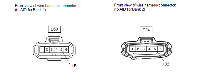 (a) Disconnect the air injection control driver (AID) connector.
(b) Turn the ignition switch to ON. (c) Measure the voltage according to the value(s) in the table below.
Standard Voltage: |
Tester Connection | Switch Condition |
Specified Condition | |
D50-5 (+B) - Body ground |
Ignition switch ON | 11 to 14 V (near battery voltage) | |
D54-5 (+B2) - Body ground |
Ignition switch ON | 11 to 14 V (near battery voltage) |
| NG |
| REPAIR OR REPLACE HARNESS OR CONNECTOR |
|
OK | |
| |
| 3. |
CHECK HARNESS AND CONNECTOR (AID - ECM, BODY GROUND) |
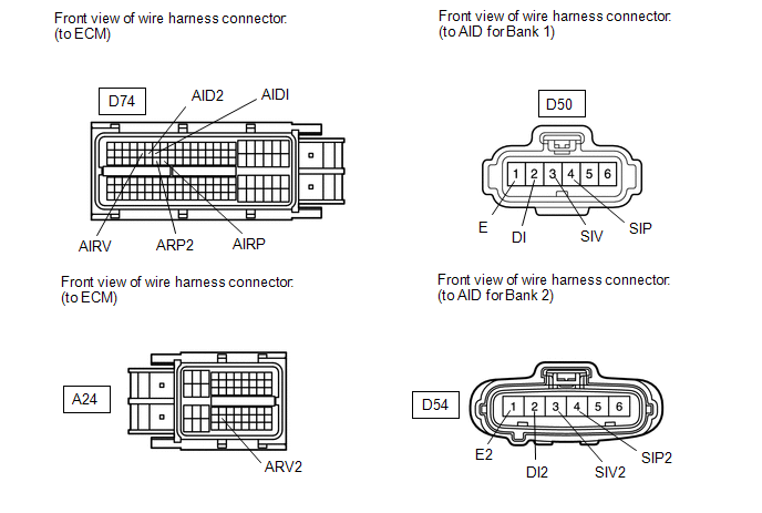 (a) Disconnect the ECM connector.
(b) Disconnect the AID connector. (c) Measure the resistance according to the value(s) in the table below.
Standard Resistance: |
Tester Connection | Condition |
Specified Condition | |
D74-54 (AIRP) - D50-4 (SIP) |
Always | Below 1 Ω | |
D74-28 (AIRV) - D50-3 (SIV) |
Always | Below 1 Ω | |
D74-53 (ARP2) - D54-4 (SIP2) |
Always | Below 1 Ω | |
A24-43 (ARV2) - D54-3 (SIV2) |
Always | Below 1 Ω | |
D74-30 (AIDI) - D50-2 (DI) |
Always | Below 1 Ω | |
D74-29 (AID2) - D54-2 (DI2) |
Always | Below 1 Ω | |
D50-1 (E) - Body ground |
Always | Below 1 Ω | |
D54-1 (E2) - Body ground |
Always | Below 1 Ω | |
D74-54 (AIRP) or D50-4 (SIP) - Body ground |
Always | 10 kΩ or higher | |
D74-28 (AIRV) or D50-3 (SIV) - Body ground |
Always | 10 kΩ or higher | |
D74-53 (ARP2) or D54-4 (SIP2) - Body ground |
Always | 10 kΩ or higher | |
A24-43 (ARV2) or D54-3 (SIV2) - Body ground |
Always | 10 kΩ or higher | |
D74-30 (AIDI) or D50-2 (DI) - Body ground |
Always | 10 kΩ or higher | |
D74-29 (AID2) or D54-2 (DI2) - Body ground |
Always | 10 kΩ or higher |
| NG |
| REPAIR OR REPLACE HARNESS OR CONNECTOR |
|
OK | |
| |
| 4. |
INSPECT AIR INJECTION CONTROL DRIVER (DI TERMINAL VOLTAGE) |
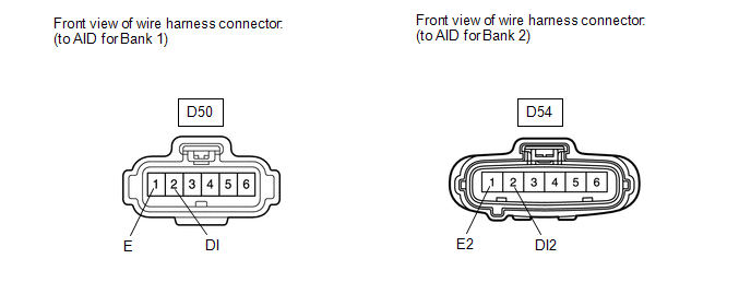 (a) Disconnect the AID connector.
(b) Turn the ignition switch to ON. (c) Measure the voltage according to the value(s) in the table below.
Standard Voltage: |
Tester Connection | Switch Condition |
Specified Condition | |
D50-2 (DI) - D50-1 (E) |
Ignition switch ON | 11 to 14 V (near battery voltage) | |
D54-2 (DI2) - D54-1 (E2) |
Ignition switch ON | 11 to 14 V (near battery voltage) |
| NG |
| REPLACE ECM |
|
OK | |
| |
| 5. |
PERFORM ACTIVE TEST USING TECHSTREAM | (a) Disconnect the AID connector.
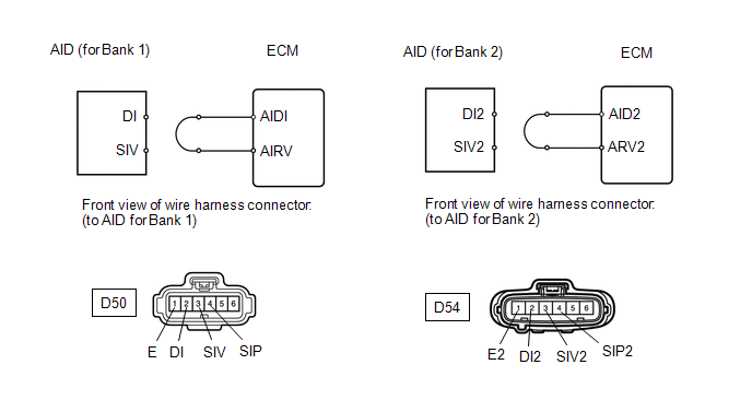 (b) Connect terminals DI and SIV or DI2 and SIV2 of the wire harness connector for the AID.
(c) Connect the Techstream to the DLC3. (d) Turn the ignition switch to ON and turn the Techstream on.
(e)
Enter the following menus: Powertrain / Engine and ECT / Utility /
Secondary Air Injection Check / Manual Mode / AIR PUMP 1: ON, ASV 1:
OPEN, AIR PUMP 2: ON, ASV 2: OPEN. HINT: When
Manual Mode is selected, the Techstream initialization (atmospheric
pressure measurement) is performed automatically. The initialization
takes 10 seconds. After the initialization, AIR PUMP and ASV operation
can be selected. (f) Start the engine. (g) Perform the AIR system forced operation while the engine is idling.
(h) Measure the voltage between the SIV and E or SIV2 and E2 terminals of the ECM connector when the AIR system is ON and OFF.
(i) Turn the ignition switch off.
NOTICE:
- Performing Secondary Air Injection Check repeatedly may cause damage to
the secondary air injection system. If it is necessary to repeat the
check, leave an interval of several minutes between System Check
operations to prevent the system from overheating.
- When performing the Secondary Air Injection Check operation after the
battery cable has been reconnected, wait for 7 minutes with the ignition
switch ON or the engine running.
- Turn the ignition switch off when the Secondary Air Injection Check operation finishes.
Standard Voltage: |
Tester Connection | Condition |
Specified Condition | | D50-3 (SIV) - D50-1 (E) |
AIR PUMP: ON, ASV: OPEN | 0.5 to 2 V | |
D54-3 (SIV2) - D54-1 (E2) | AIR PUMP: ON, ASV: OPEN |
0.5 to 2 V | | D50-3 (SIV) - D50-1 (E) |
AIR PUMP: OFF, ASV: CLOSE | 11 to 14 V | |
D54-3 (SIV2) - D54-1 (E2) | AIR PUMP: OFF, ASV: CLOSE |
11 to 14 V | (j) Connect terminals DI and SIP or DI2 and SIP2 of the wire harness connector for the AID.
 (k) Connect the Techstream to the DLC3.
(l) Turn the ignition switch to ON and turn the Techstream on. (m)
Enter the following menus: Powertrain / Engine and ECT / Utility /
Secondary Air Injection Check / Manual Mode / AIR PUMP 1: ON, ASV 1:
OPEN, AIR PUMP 2: ON, ASV 2: OPEN. HINT: When
Manual Mode is selected, the Techstream initialization (atmospheric
pressure measurement) is performed automatically. The initialization
takes 10 seconds. After the initialization, AIR PUMP and ASV operation
can be selected. (n) Start the engine. (o) Perform the AIR system forced operation while the engine is idling.
(p) Measure the voltage between the SIP and E or SIP2 and E2 terminals of the ECM connector when the AIR system is ON and OFF.
(q) Turn the ignition switch off.
NOTICE:
- Performing Secondary Air Injection Check repeatedly may cause damage to
the secondary air injection system. If it is necessary to repeat the
check, leave an interval of several minutes between System Check
operations to prevent the system from overheating.
- When performing the Secondary Air Injection Check operation after the
battery cable has been reconnected, wait for 7 minutes with the ignition
switch ON or the engine running.
- Turn the ignition switch off when the Secondary Air Injection Check operation finishes.
Standard Voltage: |
Tester Connection | Condition |
Specified Condition | | D50-4 (SIP) - D50-1 (E) |
AIR PUMP: ON, ASV: OPEN | 0.5 to 2 V | |
D54-4 (SIP2) - D54-1 (E2) | AIR PUMP: ON, ASV: OPEN |
0.5 to 2 V | | D50-4 (SIP) - D50-1 (E) |
AIR PUMP: OFF, ASV: CLOSE | 11 to 14 V | |
D54-4 (SIP2) - D54-1 (E2) | AIR PUMP: OFF, ASV: CLOSE |
11 to 14 V |
| NG |
| REPLACE ECM |
|
OK | |
| |
| 6. |
REPLACE AIR INJECTION CONTROL DRIVER (FOR BANK 1 OR BANK 2) |
(a) Replace the air injection control driver (for bank 1 or bank 2) (See page
).
|
NEXT | |
| |
| 7. |
CHECK WHETHER DTC OUTPUT RECURS | (a) Start the engine and warm it up.
(b) Turn the ignition switch off. (c) Connect the Techstream to the DLC3.
(d) Turn the ignition switch to ON. (e) Turn the Techstream on.
(f) Clear DTCs (See page ). (g) Enter the following menus: Powertrain / Engine and ECT / Utility / Secondary Air Injection Check / Automatic Mode.
(h) Start the engine after the Techstream initialization is finished. (i) Perform the System Check operation by pressing ENTER (Next).
(j) After operating the AIR system, perform the following to confirm the AIR system pending codes: Press the Exit button.
(k) Enter the following menus: Powertrain / Engine and ECT / Trouble Codes / Pending.
(l) Read DTCs. Result |
Result | Proceed to | |
No DTC is output | A | |
Other DTCs are output |
B | (m) Turn the ignition switch off.
NOTICE:
- When performing the Secondary Air Injection Check operation after the
battery cable has been reconnected, wait for 7 minutes with the ignition
switch turned to ON or the engine running.
- Turn the ignition switch off when the Secondary Air Injection Check operation finishes.
| A |
| END |
| B |
| REPLACE ECM | | 

