PARTS LOCATION ILLUSTRATION 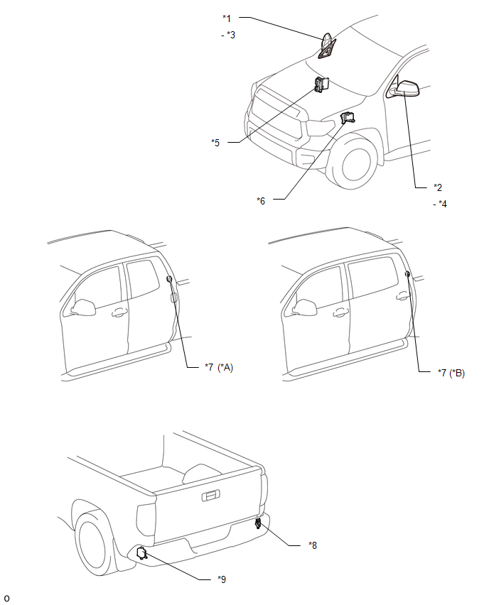
ILLUSTRATION 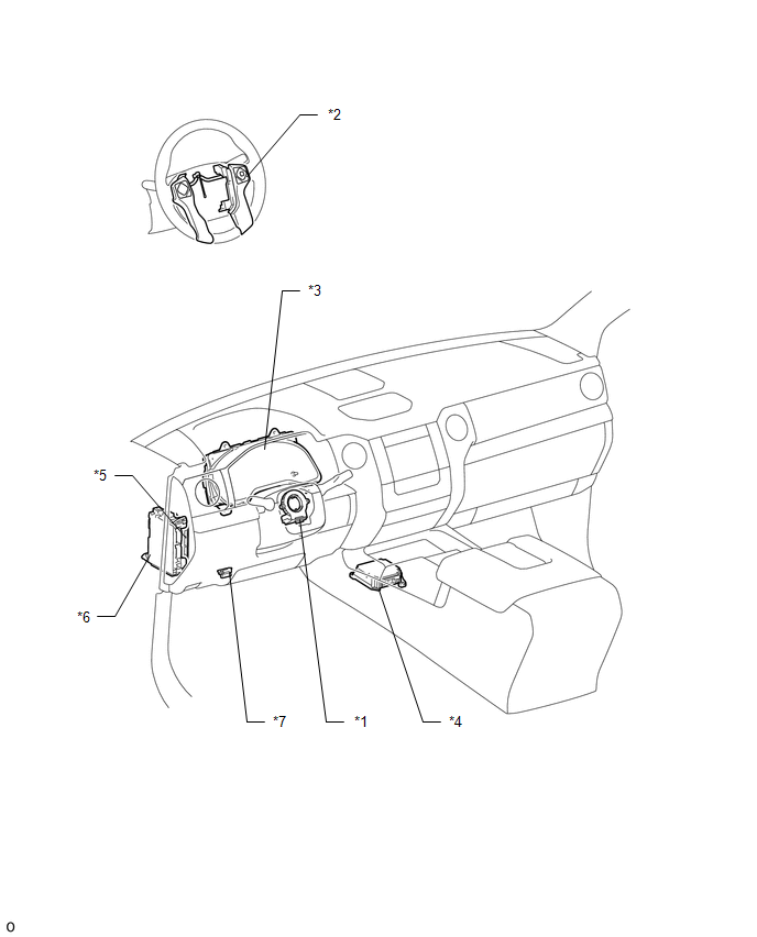
|
Toyota Tundra Service Manual > Front Door(for Double Cab): Adjustment
ADJUSTMENT CAUTION / NOTICE / HINT HINT: Before adjusting the door position for vehicles equipped with side airbags and curtain shield airbags, be sure to disconnect the battery. After adjustment, inspect the SRS warning light and check for DTC (see page ). Use the same procedures for the RH side an ...


