Toyota Tundra Service Manual: Power Source Circuit

DESCRIPTION

This circuit provides power to operate the blind spot monitor sensor.

WIRING DIAGRAM

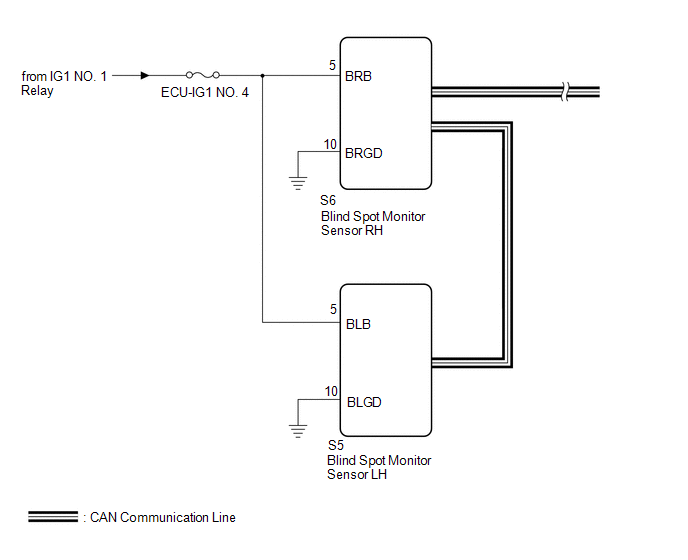
CAUTION / NOTICE / HINT

NOTICE:

Inspect the fuses for circuits related to this system before performing the following procedure.

PROCEDURE

1.

CHECK HARNESS AND CONNECTOR (BLIND SPOT MONITOR SENSOR RH, BLIND SPOT MONITOR SENSOR LH - BATTERY AND BODY GROUND)

(a) Disconnect the blind spot monitor sensor RH connector.

*a

Front view of wire harness connector

(to Blind Spot Monitor Sensor RH)

*b

Front view of wire harness connector

(to Blind Spot Monitor Sensor LH)

(b) Disconnect the blind spot monitor sensor LH connector.

(c) Measure the resistance according to the value(s) in the table below.

Standard Resistance:

Tester Connection

Condition

Specified Condition

S6-10 (BRGD) - Body ground or other terminal

Always

Below 1 Ω

S5-10 (BLGD) - Body ground or other terminal

Always

Below 1 Ω

(d) Measure the voltage according to the value(s) in the table below.

Standard Voltage:

Tester Connection

Switch Condition

Specified Condition

S6-5 (BRB) - Body ground

Ignition switch ON

11 to 14 V

S6-5 (BRB) - Body ground

Ignition switch off

Below 1 V

S5-5 (BLB) - Body ground

Ignition switch ON

11 to 14 V

S5-5 (BLB) - Body ground

Ignition switch off

Below 1 V

OK

PROCEED TO NEXT SUSPECTED AREA SHOWN IN PROBLEM SYMPTOMS TABLE

NG

REPAIR OR REPLACE HARNESS OR CONNECTOR

    Parts Location

    Precaution

    See More:

    Toyota Tundra Service Manual > Lighting System: Interior Light Auto Cut Circuit
    DESCRIPTION When the battery saving control operates, the main body ECU (multiplex network body ECU) controls the operation of the DOME CUT relay that is built into the driver side junction block assembly to turn off the interior lights. WIRING DIAGRAM CAUTION / NOTICE / HINT NOTICE: Inspect the fus ...

    Toyota Tundra Owners Manual

    Toyota Tundra Service Manual

    © 2024 Copyright www.ttundra.com
    0.019