DESCRIPTION The clearance warning buzzer is installed in the combination meter assembly. WIRING DIAGRAM 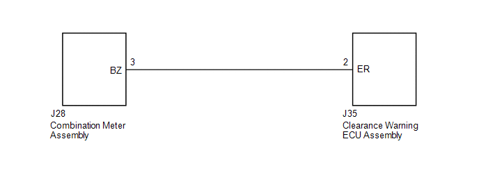 PROCEDURE
(a) Disconnect the J35 clearance warning ECU assembly connector. (b) Disconnect the J28 combination meter assembly connector. (c) Measure the resistance according to the value(s) in the table below. Standard Resistance:
(a) Replace the combination meter assembly with a normally functioning or new one (See page
(b) Check that the clearance warning buzzer operates normally. OK: Clearance warning buzzer operates normally.
|
Toyota Tundra Service Manual > Axle: Front Axle Hub Bolt
ComponentsCOMPONENTS ILLUSTRATION ReplacementREPLACEMENT CAUTION / NOTICE / HINT HINT: Use the same procedures for the LH side and RH side. The procedures listed below are for the LH side. PROCEDURE 1. REMOVE FRONT WHEEL 2. DISCONNECT FRONT DISC BRAKE CALIPER ASSEMBLY LH 3. REMOVE FRONT DISC 4. REM ...


