DESCRIPTION This circuit is the power source circuit to operate the clearance warning ECU assembly. WIRING DIAGRAM 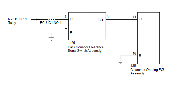 CAUTION / NOTICE / HINT NOTICE: Inspect the fuses for circuits related to this system before performing the following procedure. PROCEDURE
(b) Measure the voltage according to the value(s) in the table below. Standard Voltage:
(c) Measure the resistance according to the value(s) in the table below. Standard Resistance:
(a) Remove the back sonar or clearance sonar switch assembly (See page
(b) Inspect the back sonar or clearance sonar switch assembly (See page
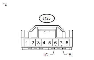
(a) Disconnect the J35 clearance warning ECU assembly connector. (b) Disconnect the J125 back sonar or clearance sonar switch assembly connector. (c) Measure the resistance according to the value(s) in the table below. Standard Resistance:
|
Toyota Tundra Service Manual > Audio And Visual System: Data Signal Circuit between Radio Receiver and Stereo Jack Adapter
DESCRIPTION The No. 1 stereo jack adapter assembly sends the sound data signal or image data signal from a device to the radio and display receiver assembly via this circuit. WIRING DIAGRAM PROCEDURE 1. CHECK HARNESS AND CONNECTOR (RADIO AND DISPLAY RECEIVER ASSEMBLY - NO. 1 STEREO JACK ADAPTER ASSE ...


 ).
).
