DESCRIPTION The No. 1 ultrasonic sensor sends and receives ultrasonic waves. Based on the received wave, the sensor calculates the approximate distance value between the vehicle and the obstacle, and sends the distance value as a signal to the clearance warning ECU assembly. WIRING DIAGRAM 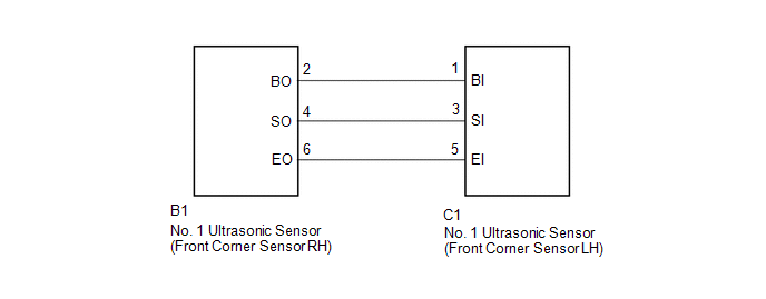 PROCEDURE
(a) Remove the No. 1 ultrasonic sensor (front corner sensor LH) (See page
(b) Inspect the No. 1 ultrasonic sensor (front corner sensor LH) (See page
(a) Disconnect the C1 No. 1 ultrasonic sensor (front corner sensor LH) connector. (b) Disconnect the B1 No. 1 ultrasonic sensor (front corner sensor RH) connector. (c) Measure the resistance according to the value(s) in the table below. Standard Resistance:
|
Toyota Tundra Service Manual > Lumbar Support Adjuster Assembly: Inspection
INSPECTION PROCEDURE 1. INSPECT LUMBAR SUPPORT ADJUSTER ASSEMBLY LH (w/ Seat Position Memory System) (a) Check the operation of the lumbar support adjuster assembly LH. (1) Apply battery voltage to the lumbar support motor LH connector, and check that the lumbar support adjuster assembly LH operates ...


