Toyota Tundra Service Manual: Parts Location

PARTS LOCATION

ILLUSTRATION
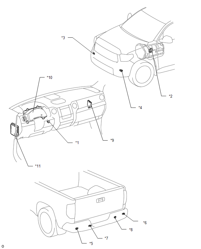
*1

BACK SONAR OR CLEARANCE SONAR SWITCH ASSEMBLY

*2

PARK/NEUTRAL POSITION SWITCH ASSEMBLY

*3

NO. 1 ULTRASONIC SENSOR (FRONT CORNER SENSOR RH)

*4

NO. 1 ULTRASONIC SENSOR (FRONT CORNER SENSOR LH)

*5

NO. 2 ULTRASONIC SENSOR (FRONT CORNER SENSOR LH)

*6

NO. 2 ULTRASONIC SENSOR (REAR CORNER SENSOR RH)

*7

NO. 3 ULTRASONIC SENSOR (REAR CENTER SENSOR LH)

*8

NO. 3 ULTRASONIC SENSOR (REAR CENTER SENSOR RH)

*9

CLEARANCE WARNING ECU ASSEMBLY

*10

COMBINATION METER ASSEMBLY

*11

COWL SIDE JUNCTION BLOCK LH

- ECU-IG1 NO.4 FUSE

- BKUP LP FUSE (for Floor Shift Type)

-

-

    Park / Neutral Position Switch Circuit

    Precaution

    See More:

    Toyota Tundra Service Manual > Front Propeller Shaft Assembly: Installation
    INSTALLATION PROCEDURE 1. INSTALL FRONT PROPELLER SHAFT (a) Completely remove any oil or the like and clean the contact surfaces of the propeller shaft flange, differential flange and transfer flange. (b) for Front Differential Side: (1) Align the matchmarks on the differential and propeller shaft f ...

    Toyota Tundra Owners Manual

    Toyota Tundra Service Manual

    © 2025 Copyright www.ttundra.com
    0.0182