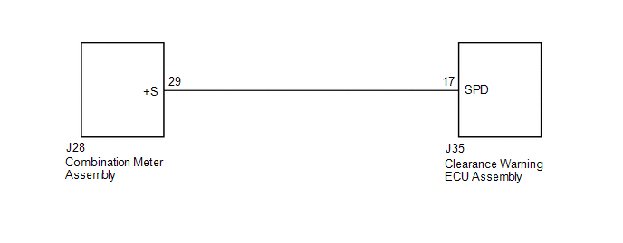
Toyota Tundra Service Manual: Vehicle Speed Signal Circuit

WIRING DIAGRAM

PROCEDURE

1.

CHECK COMBINATION METER ASSEMBLY (SPEED SIGNAL)

(a) Disconnect the clearance warning ECU assembly connector.

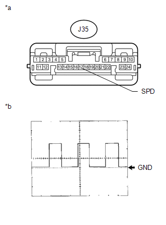
(b) Using an oscilloscope, check the signal waveform of the combination meter assembly.

Measurement Condition

Item

Content

Terminal No. (Symbol)

J35-17 (SPD) - Body ground

Tool Setting

5 V/DIV., 20 msec./DIV.

Condition

Drive vehicle at 20 km/h (12 mph)

OK:

Refer to the illustration.

HINT:

As the vehicle speed increases, the wave length shortens.

Text in Illustration

*a

Front view of wire harness connector

(to Clearance Warning ECU Assembly)

*b

Waveform

OK

PROCEED TO NEXT SUSPECTED AREA SHOWN IN PROBLEM SYMPTOMS TABLE

NG

2.

CHECK HARNESS AND CONNECTOR (CLEARANCE WARNING ECU ASSEMBLY - COMBINATION METER ASSEMBLY)

(a) Disconnect the J35 clearance warning ECU assembly connector.

(b) Disconnect the J28 combination meter assembly connector.

(c) Measure the resistance according to the value(s) in the table below.

Standard Resistance:

Tester Connection

Condition

Specified Condition

J35-17 (SPD) - J28-29 (+S)

Always

Below 1 Ω

J35-17 (SPD) - Body ground

Always

10 kΩ or higher

OK

GO TO METER / GAUGE SYSTEM

NG

REPAIR OR REPLACE HARNESS OR CONNECTOR

    Terminals Of Ecu

    Rear Cross Traffic Alert Buzzer(for Crewmax)

    See More:

    Toyota Tundra Service Manual > Audio And Visual System: Dtc Check / Clear
    DTC CHECK / CLEAR 1. START DIAGNOSTIC MODE HINT: Illustrations may differ from the actual vehicle screen depending on the device settings and options. Therefore, some detailed areas may not be shown exactly the same as on the actual vehicle screen. If the system cannot enter the diagnostic mode, rep ...

    Toyota Tundra Owners Manual

    Toyota Tundra Service Manual

    © 2024 Copyright www.ttundra.com
    0.0101