|
Terminal No. (Symbol) | Wiring Color |
Terminal Description | Condition |
Specified Condition |
|
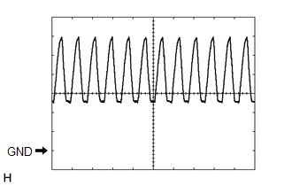
J35-2 (ER) - J35-16 (E) |
V - W-B | Clearance warning buzzer |
Ignition
switch ON, back sonar or clearance sonar switch assembly ON, shift
lever in R and sensor is detecting state (buzzer sounding) |
Pulse generation (See waveform 1) |
|
Buzzer not sounding | 11 to 14 V |
|
J35-3 (BOF) - J35-16 (E) |
R - W-B | Ultrasonic sensor power source |
Ignition switch ON, back sonar or clearance sonar switch assembly ON |
7.2 to 8.8 V |
|
J35-4 (E5) - J35-16 (E) |
G - W-B | ECU ground |
Always | Below 1 Ω |
|
J35-5 (SOF) - J35-4 (E5) |
L - G | Front sensor communication signal |
Ignition switch ON, back sonar or clearance sonar switch assembly ON, shift lever not in R |
Pulse generation (See waveform 3) |
|
J35-6 (PL) - J35-16 (E) |
B - W-B | Parking position signal |
Ignition switch ON, shift lever not in P |
Below 1.5 V |
| Ignition switch ON, shift lever in P |
7 V or higher |
|
J35-7 (L1) - J35-16 (E) |
G - W-B | Rear corner ultrasonic sensor RH |
Clearance warning indicator LED for rear corner sensor RH illuminates |
Below 3 V |
|
J35-8 (L2) - J35-16 (E) |
GR - W-B | Rear corner ultrasonic sensor LH |
Clearance warning indicator LED for rear corner sensor RH illuminates |
Below 3 V |
|
J35-9 (L4) - J35-16 (E) |
W - W-B | Front corner ultrasonic sensor RH |
Clearance warning indicator LED for front corner sensor RH illuminates |
Below 3 V |
|
J35-10 (L10) - J35-16 (E) |
R - W-B | Clearance warning ECU signal |
Clearance warning indicator's operation indicator illuminates |
Below 3 V |
|
J35-12 (BOR) - J35-16 (E) |
P - W-B | Ultrasonic sensor power source |
Ignition switch ON, back sonar or clearance sonar switch assembly ON |
7.2 to 8.8 V |
|
J35-13 (E1) - J35-16 (E) |
GR - W-B | ECU ground |
Always | Below 1 Ω |
|
J35-14 (SOR) - J35-13 (E1) |
LG - GR | Rear sensor communication signal |
Ignition switch ON, back sonar or clearance sonar switch assembly ON, shift lever in R |
Pulse generation (See waveform 2) |
|
J35-17 (SPD) - J35-16 (E) |
V - W-B | Vehicle speed signal |
Ignition switch ON, drive wheels are turned slowly |
Alternating between 1.5 to 4.5 V |
|
J35-21 (RL) - J35-16 (E) |
W - W-B | Reverse position signal |
Ignition switch ON, shift lever not in R |
Below 1.5 V |
| Ignition switch ON, shift lever in R |
7 V or higher |
|
J35-23 (L3) - J35-16 (E) |
SB - W-B | Rear center ultrasonic sensor |
Clearance warning indicator LED for rear center sensor illuminates |
Below 3 V |
|
J35-24 (L5) - J35-16 (E) |
LG - W-B | Front corner ultrasonic sensor LH |
Clearance warning indicator LED for front corner sensor LH illuminates |
Below 3 V |
 Measurement Condition
 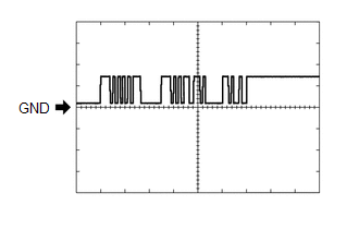 Measurement Condition

